Untitled - Technische Universiteit Eindhoven
Untitled - Technische Universiteit Eindhoven
Untitled - Technische Universiteit Eindhoven
- No tags were found...

Create successful ePaper yourself
Turn your PDF publications into a flip-book with our unique Google optimized e-Paper software.
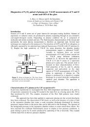
8.4. Results and discussion 127value [-]10.90.80.70.60.50.40.30.20.1∆ P normS wµ o,normw SA w00 5 10 15 20 25 30 35 40PV injected [-]S w[-]0.50.450.40.350.30.250.20.150.10.05t=0t=13 min.t=3 min.t=48 min.t=198 min.t=855 min.t=98 min.0-0.03 -0.02 -0.01 0 0.01 0.02 0.03z [m]Fig. 8.9: (left) Example simulation of Case B. Shown are the normalized differential pressure∆P norm , the average water saturation S w , the normalized average viscosity of theoil phase µ o,norm and the average silicic acid fraction wwSA versus PV injected. Q is0.1 ml min −1 and k is 0.323×10 −3 s −1 . (right) Saturation profiles at different timeintervals.a = 4. The total simulation time is 815 minutes. With respect to the results of CaseB we focus on the (normalized) differential pressure over the core, ∆P norm , versus time,which is shown in Figure 8.9 (left-hand graph). It can be observed that ∆P norm decreasesto 0.5 as the initial pore volume of mixture has been injected. This is attributed to therelatively fast displacement of the oil originally present in the system with the mixture,which has a lower viscosity. The normalized average viscosity of the oleic phase is plottedas well in Figure 8.9 and shows an initial decrease to about 0.45. Subsequently, thedifferential pressure increases up to the point at which 10 PV are injected. This is due tothe concurrent mass transfer of TMOS from oil to water and the resulting increase of theaverage water saturation S w , and hence, the decreasing average relative permeability foroil. Some profiles of S w at different time intervals are shown in the right-hand graph ofFigure 8.9. As the average water saturation starts to increase it becomes greater than theirreducible water saturation S wi and the relative permeability for water becomes greaterthan zero. Some water is therefore produced which counteracts the increase of S w due tothe mass transfer. This causes that S w , and hence ∆P norm , start to decrease after 10 PVhas been injected. However, the drainage is slow and some TMOS is still transferred fromthe oleic to the aqueous phase. Finally, the average fraction of silicic acid wwSA versusthe injected amount of mixture is shown in Figure 8.9. The fraction grows from zero to0.15 in the initial period (5 PV injected) after which is increases gradually to 0.22 in theremainder of the simulation.8.4.5 Case B. Continuous injection: effect of main parametersThe main parameter considered for Case B is the injection rate Q. In the left-hand graphof Figure 8.10 the effect of the injection rate Q on the normalized differential pressure∆P norm is demonstrated. The rate Q was varied between 0.1 and 2 ml min −1 . All profiles