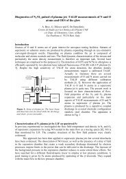
Untitled - Technische Universiteit Eindhoven
Untitled - Technische Universiteit Eindhoven
Untitled - Technische Universiteit Eindhoven
- No tags were found...

You also want an ePaper? Increase the reach of your titles
YUMPU automatically turns print PDFs into web optimized ePapers that Google loves.
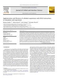
128 8. Model of reactive transport of an oil-soluble chemical in porous media10.90.832.51 mPa s10 mPa s100 mPa s1000 mPa s∆ P norm[-]0.70.60.50.40.30.20.10.1 ml min -10.2 ml min -10.5 ml min -11 ml min -12 ml min -1 0 5 10 15 20 25 30 35 40∆ P norm[-]21.510.500 5 10 15 20 25 30 35 40PV injected [-]0PV injected [-]Fig. 8.10: (left) The effect of the injection rate Q on the normalized differential pressure profiles.The reaction rate k is 0.323×10 −3 s −1 . (right) The effect of the aqueous phaseviscosity µ w (see Legend) on the pressure profiles (with Q = 0.1 ml min −1 ).show an initial decrease of ∆P norm . The minimum pressure, which is found after about1 PV has been injected, is the lowest for the highest injection rate and increases withdecreasing injection rate. The maximum that follows the minimum is the highest for thelowest injection rate and decreases with increasing injection rate. In addition, the amountof PV injected at which the maximum is found increases with increasing Q.Finally, the effect of gelation on the pressure profiles is considered. Though the gelreaction was not taken into account in the model, we can qualitatively analyse the effectby calculating the pressure profiles using a viscosity µ w higher than that of water. Inabsence of a gel reaction model the viscosity can only be chosen constant. The right-handgraph of Figure 8.10 shows the effect of µ w on the pressure profiles. The viscosity µ whas little influence on the initial decrease of ∆P norm since the water is not mobilized inthe initial period. However, after the first 10 PV of solution has been injected the watersaturation has increased significantly. Hence, the relative permeability of oil is decreasedand the water is slowly drained. Given a flow rate Q the pressure increases with increasingviscosity µ w .8.5 ConclusionThe physical-mathematical model can be used to simulate the reactive transport mechanismsof TMOS in linear cores or simple reservoirs. The simulated mass transfer profilesagreed well with the experimental mass transfer profiles measured in the core injectionexperiments, especially for the unbuffered system and the acid-catalyzed system. Thesensitivity analysis of the parameters showed that in case of a low injection rate versusa high reaction rate the mass transfer profiles and the profiles of the reaction productsbecome non-uniform. Secondly, lowering the injection rate or increasing the reaction ratepromotes a higher end-point water saturation and larger amount of gel formed (providedan excess of mixture was injected). The latter has important implications for the reduc-