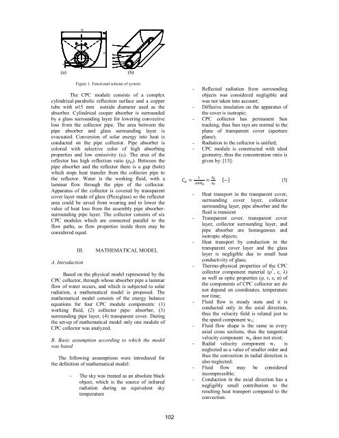
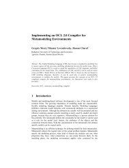
Waa5g(a)H64321(b)LFigure 1. Functional scheme of systemThe CPC module consists of a complexcylindrical-parabolic reflection surface and a coppertube with ø15 mm outside diameter used as theabsorber. Cylindrical cooper absorber is surroundedby a glass surrounding layer for lowering convectiveloss from the collector pipe. The area between thepipe absorber and glass surrounding layer isevacuated. Conversion of solar energy into heat isconducted on the pipe collector. Pipe absorber iscolored with selective color of high absorbingproperties and low emissivity (ε r ). The area of thereflector has high reflection ratio (ρ m ). Between thepipe absorber and the reflector there is a gap (hole)which stops heat transfer from the collector pipe tothe reflector. Water is the working fluid, with alaminar flow through the pipe of the collector.Apparatus of the collector is covered by transparentcover layer made of glass (Plexiglass) so the reflectorarea could be saved from wearing and to lower thevalue of heat loss from the assembly pipe absorbersurroundingpipe layer. The collector consists of sixCPC modules which are connected parallel to theflow paths, so flow properties inside them may beconsidered equal.III.A. IntroductionMATHEMATICAL MODELBased on the physical model represented by theCPC collector, through whose absorber pipe a laminarflow of water occurs, and which is subjected to solarradiation, a mathematical model is proposed. Themathematical model consists of the energy balanceequations for four CPC module components: (1)working fluid, (2) collector pipe- absorber, (3)surrounding pipe layer, (4) transparent cover. Duringthe set-up of mathematical model only one module ofCPC collector was analyzed.B. Basic assumption according to which the modelwas basedThe following assumptions were introduced forthe definition of mathematical model:- The sky was treated as an absolute blackobject, which is the source of infraredradiation during an equivalent skytemperature - Reflected radiation from surroundingobjects was considered negligible andwas not taken into account;- Diffusive insulation on the apparatus ofthe cover is isotropic;- CPC collector has permanent Suntracking, thus Sun rays are normal to theplane of transparent cover (apertureplane);- Radiation to the collector is unified;- CPC module is constructed with idealgeometry, thus the concentration ratio isgiven by: [13]: (1)- Heat transport in the transparent cover,surrounding cover layer, collectorsurrounding layer, pipe absorber and thefluid is transient- Transparent cover, transparent coverlayer, collector surrounding layer, andpipe absorber are homogenous andisotropic objects;- Heat transport by conduction in thetransparent cover layer and the glasslayer is negligible due to small heatconductivity of glass;- Thermo-physical properties of the CPCcollector component material (ρ * , c, λ)as well as optic properties (ρ, τ, ε, α) ofthe components of CPC collector are donot depend on coordinates, temperaturenor time;- Fluid flow is steady state and it isconducted only in the axial direction,thus the velocity field is related just tothe speed component w z ;- Fluid flow shape is the same in everyaxial cross sections, thus the tangentialvelocity component w φ does not exist;- Radial velocity component w r isneglected as a value of smaller order andthus the convection in radial direction isalso neglected;- Fluid flow may be consideredincompressible;- Conduction in the axial direction has anegligibly small contribution to theresulting heat transport compared to theconvection.102
C. Energy balance equationMathematical model consists of equations ofenergy balance for all of the four components of theCPC modle, relations for determining heat transfercoefficient, relations for radiation absorbed by therelevant system components. In order to gain a unifiedsolution from the system of equations, initial andboundary conditions are defined. With apredetermined assumptions, equations of energybalance may be written as:(1) For the working fluidEnergy balance for an elementary fluid volumeof dz length in the axial direction, after sorting, maybe written as:T* * f c A *c A*wf p f f f p f f ztU T 2/ r T rr f f r , oTfzWhere ∗ , i w z represent density, specificheat, velocity in the axial direction of the elementary*fluid volume, respectively A 2 f r r , iis the area ofthe cross section of the elementary fluid particle. Thesecond term on the right hanside of the equation (2)represents heat gained from the outer side of thecollector pipeBoundary condition for this equation is:za z = 0,fin(2)T T . (3)(2) For the collector absorber pipeEnergy balance for elementary part of the collector ofdz length in the axial direction may be written as;* * TrTr* r cr Ar r Ar hc, r / ehr, r / et z zTr Te 2 rr , o-U r / fTr Tf2 rr , o qb, rqd , r2 rr , o (4)Where λ r , ∗ i c r are head conductioncoefficient, density and specific heat for elementary* 2 2pipe volume, respectively. Ar rr, o rr, i is thearea of the cross section of elementary part of thecollector pipe. The first term on the right hand side ofthe equation (4) represents heat transport byconduction in the axial direction of the collector, thesecond is the heat loss due to convention and radiationbetween the collector pipe and the surrounding layerof the collector pipe, the third term represents heatgiven to the working fluid, and the fourth representsheat gained via solar radiationBoundary conditions for this equation are:T za z 0, r 0 ; (5)zza z L,T r 0(6)z(3) For the transparent cover of the pipecollectorEnergy balance for the elementary part of thesurrounding layer of the collector pipe of dz length iswritten as:* * T eece Ae hc, r/ ehr, r/eTr Te 2 r,ot-hc, e/ chr, e/cTeTc2 re , o qb, eqd , e2 r(7)r,o∗Where i c e are density and specific heat og the* 2 2surrounding layer of the collector Ar re, o re, iis the area of the cross section of elementary part ofthe surraounding layer of the collector. The secondterm on the right hand side of the equation (7) is theheat lost due to radiation from the surrounding layerof the collector to the transparent cover(4) For the transparent coverEnergy balance for the elementary part of thetransparent cover of the concentrating collector, withdz length in the z direction and W width, may bewritten as:* * T cccc Ac hc, e/ chr, e/cTe Tct2 re , o h c, c/ aTc Ta W hr, c/sTc TsWq b , cq d , c2 r r , o(8)*A c W is the area of the cross section ofelementary part of the transparent cover of thecollector. The second term on the right hand side ofthe equation (8) is the heat lost due to convectionfrom the transparent cover to the environment, thethird term is the heat lost due to radiation between thetransparent cover and the sky.D. Initial conditionsIt was assumed for the initial conditions that inthe initial time point the temperature field in allcomponents is equal to the environment temperatureT a , while the fluid temperature at the inlet is constantin timeZa t 0, TfTr Te Tc Ta(9)Za z 0, T fT in(10)103
- Page 1 and 2:
4 4 th IEEE International Symposium
- Page 3 and 4:
EXPRES 20124 th International Sympo
- Page 5 and 6:
Application of Thermopile Technolog
- Page 7 and 8:
Design of a Solar Hybrid System....
- Page 9 and 10:
___________________________________
- Page 11 and 12:
environmental protection and global
- Page 13 and 14:
But can we use the human body sweat
- Page 15 and 16:
IX. REFERENCES[1] Todorovic B. Cvje
- Page 17 and 18:
QQ⎛ Λt⎞=⎜⎟⎝ Λ ⎠Nt Nwh
- Page 19 and 20:
Analysis of the Energy-Optimum of H
- Page 21 and 22:
V. OBJECTIVE FUNCTIONThe objective
- Page 23 and 24:
The Set-Up Geometry of Sun Collecto
- Page 25 and 26:
continuous east-west sun collector
- Page 27 and 28:
continuously measure the thermal ch
- Page 29 and 30:
CEvaluation of measurement resultsA
- Page 31 and 32:
Application of Thermopile Technolog
- Page 33 and 34:
Temperature of the components [C]90
- Page 35 and 36:
nighttime, to weather or to the cha
- Page 37 and 38:
η uη u0.50.40.30.20.1T 1 - 400K0.
- Page 39 and 40:
Figure 10. . SPS Concept illustrati
- Page 41 and 42:
[16] Zoya B. Popović: Wireless Pow
- Page 43 and 44:
25.0020.0015.0010.005.000.00Figure
- Page 45 and 46:
· ℃ 0.0738 · 1.209 0.0892
- Page 47 and 48:
use may be advantageous not only in
- Page 49 and 50:
To find the reasons for this disagr
- Page 51 and 52:
Toward Future: Positive Net-Energy
- Page 53 and 54: EnergyPlus environment, we used mod
- Page 55 and 56: To keep future energy consumption d
- Page 57 and 58: A New Calculation Method to Analyse
- Page 59 and 60: On Fig. 3. can be seen the areas th
- Page 61 and 62: Present and Future of Geothermal En
- Page 63 and 64: TABLE II.THE TEMPERATURE DATA AND C
- Page 65 and 66: Error in Water Meter Measuring at W
- Page 67 and 68: III.RESULTS OF MEASURMENTSEach meas
- Page 69 and 70: TABLE I.THE AVERAGE VALUE OF THERMA
- Page 71 and 72: If the walls of the DHEs are made o
- Page 73 and 74: Environmental External Costs Associ
- Page 75 and 76: iodiesel production facility with a
- Page 77 and 78: Contribution of unit processesto ex
- Page 79 and 80: Heat Pump News in HungaryBéla Ád
- Page 81 and 82: Thermal Comfort Measurements In Lar
- Page 83 and 84: IV.DISCUSSIONThe sample frequencies
- Page 85 and 86: For a Clear View of Traditional and
- Page 87 and 88: esults in geographically distribute
- Page 89 and 90: Design of a Solar Hybrid SystemMari
- Page 91 and 92: Maintaining the set point temperatu
- Page 93 and 94: Decision system theory model of ope
- Page 95 and 96: parameter of pump in the function o
- Page 97 and 98: Importance and Value of Predictive
- Page 99 and 100: D. Overview of existing boiler oper
- Page 101 and 102: HEAVY FUEL OIL FIRED, STEAMNATURAL
- Page 103: MATHEMATICAL MODEL AND NUMERICAL SI
- Page 107 and 108: Discretization energy balance equat
- Page 109 and 110: T ulf=32 º C, A - m =0.00162 kg/s,
- Page 111 and 112: Comparison of Heat Pump and MicroCH
- Page 113 and 114: the microCHP development. The energ
- Page 115 and 116: control and stabilizer must be deve
- Page 117 and 118: In Figure 1, in relation to the ord
- Page 119 and 120: NPCC BHXOBYNI x1I x2I x3I x4LO YKYO
- Page 121 and 122: exchange, as in reality, economies
- Page 123 and 124: esponsibilities for consequences, o
- Page 125 and 126: Coca-Cola Enterprise Inc had approx
- Page 127 and 128: Flow Pattern Map for In Tube Evapor
- Page 129 and 130: circumference with a liquid film. T
- Page 131 and 132: Tube diameter: d 6 mm W Heat flux
- Page 133 and 134: Realization of Concurrent Programmi
- Page 135 and 136: applications the development, optim
- Page 137 and 138: Renewable energy sources in automob
- Page 139 and 140: commercial arrays can be built at b
- Page 141 and 142: of multiple thin films produced usi
- Page 143: EXPRES 20124 th International Sympo