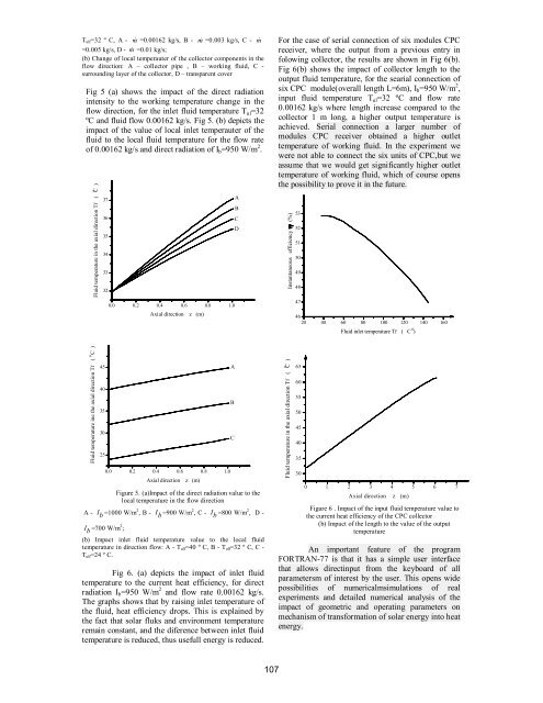
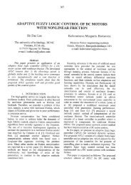
the temperature of the node (i) is obtained of thetransparent cover for the time step (1), T :1c,i1 t0 0Tc , i * *d1Tc , i d2Te,i d3 c c c A c zB. The method for solving algebraic equations(26)Discretization equation of energy balancecomponents for the corresponding receiver modulesCPC gets a set of coupled linear algebraic equations,with the total number of equations equals the numberof nodal points in the axial direction for all fourcomponents. Since .the thermophysical properties ofworking fluid (water) depends on the temperature,there is a need for an iterative method of solving.During the solving this system of algebraicequations were introduced two temperature fields, theprevious time instant (0) and the next moment in time(1). Before solving each new temperature field (1),shall be converted thermophysical properties of water,the corresponding coefficient of heat transfercoefficients and equations themselves. For the initialtemperature field is taken that the temperature of allcomponents of nodal points of equal temperatureenvironment. Nodal point i=1 for the working fluid atthe entrance to the pipe receiver has a constanttemperature T in for the each time instant. Aftersolving the system of algebraic equations, the newtemperature field (1) now becomes the temperaturefield for the previous time instant (0). Solvingprocedure continues until the temperature differencebetween two successive iterations, for all nodal pointsare not less than the pre-ser errors ε e . After severaltest, we found that the ε e =10 -5 (°C) i Δt=0.0005 sFor the implementation of numericalprocedures of solving the mathematical model of fluidflow ine the pipe CPC receiver, and thermal behaviorof other components of the receiver in the programhas been developed in FORTRAN-77, whose algoritmTABLE I.is shown in Fig.7.CPC MODULE DATADimensionsrr , i 0.0065 m, r,o 0.0075m , r , 0.01m re , o 0,012m, 0.005m, 0.065[ ] Le i ,W m , 1[ H 0.0465[ m ]Optical properties r 0.05 , e c 0.85 , e c 0.05 , r 0.15 , m 0.85 , e c 0.90 , r 0.95 , e c 0.05Thermo-physical properties33e c 2700[ kg / m ] , dr 8930[ kg / m ] ,ce cc 840 J / kgK, c 383 J / kgKr 395 W / mKr , The procedure begins with entering the calculationof basic geometric characteristics of CPC receiver, thenumber of nodal point, thermophysic and opticalproperties of system components, working fluid inlettemperature, intensity of solar radiation, and windvelocity.C. The results of numerical experimentsDuring the calculation, it was assumed that thesolar rays fall normal to the aperture plane. It wasassumed that all off the radiation falls to the aperturedirectly. In the table I. Dimensions ,thermophisicalproperties for the CPC module, for which thenumerical simulation was conducted, is given.During the calculations, envirponment temperaturewas T a =28 ºC , wind speed v=2 m/s were keptconstant. For direct solar radiation I b =950 W/m 2 , inletfluid temperature T ul =32 ºC i and different flowvalues, the values of local temperautere of theworking fluid in the direction of the flow are given inFig. 4. (a) which shows that by increasing fluid flowrate output temperature is reduced. Fig. 4. (b) showsthe change of temperature of the collector pipe,working fluid, surrounding collector pipe layer, andtransparent cover in the flow direction, for the directsolar radiation I b =950 W/m 2 , inlet temperature of thefluid T ul =32 ºC and working fluid flow 0.00162 kg/s.Fluid temperature in the axial direction Tf ( C )o373635343332Temperature components of the collectoroin the axial direction Tr, Tf, Te i Tc ( C )0.0 0.2 0.4 0.6 0.8 1.04844424038363432Axial direction z (m)30C28D0.0 0.2 0.4 0.6 0.8 1.0Axial direction z (m)Figure 4. (a) Impact of the mass flow rate to local fluid temperaturein the flow directionABCDAB106
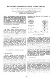
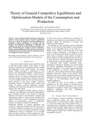
T ulf=32 º C, A - m =0.00162 kg/s, B - m =0.003 kg/s, C - m=0.005 kg/s, D - m =0.01 kg/s;(b) Change of local temperauter of the collector components in theflow direction: A – collector pipe , B – working fluid, C -surrounding layer of the collector, D – transparent coverFig 5 (a) shows the impact of the direct radiationintensity to the working temperature change in theflow direction, for the inlet fluid temperature T ul =32ºC and fluid flow 0.00162 kg/s. Fig 5. (b) depicts theimpact of the value of local inlet temperauter of thefluid to the local fluid temperature for the flow rateof 0.00162 kg/s and direct radiation of I b =950 W/m 2 .Fluid temperature in the axial direction Tf ( C )o3736353433320.0 0.2 0.4 0.6 0.8 1.0Axial direction z (m)ABCDFor the case of serial connection of six modules CPCreceiver, where the output from a previous entry infolowing collector, the results are shown in Fig 6(b).Fig 6(b) shows the impact of collector length to theoutput fluid temperature, for the searial connection ofsix CPC module(overall length L=6m), I b =950 W/m 2 ,input fluid temperature T ul =32 ºC and flow rate0.00162 kg/s where length increase compared to thecollector 1 m long, a higher output temperature isachieved. Serial connection a larger number ofmodules CPC receiver obtained a higher outlettemperature of working fluid. In the experiment wewere not able to connect the six units of CPC,but weassume that we would get significantly higher outlettemperature of working fluid, which of course opensthe possibility to prove it in the future.Instantaneous efficiency (%)535251504948474620 40 60 80 100 120 140 160oFluid inlet temperature Tf ( C )Fluid temperature ine the axial direction Tf ( C )o45 A403530250.0 0.2 0.4 0.6 0.8 1.0Axial direction z (m)Figure 5. (a)Impact of the direct radiation value to thelocal temperature in the flow directionA - I b =1000 W/m 2 , B - I b =900 W/m 2 , C - I b =800 W/m 2 , D -I b=700 W/m 2 ;(b) Impact inlet fluid temperature value to the local fluidtemperature in direction flow: A - T ulf=40 º C, B - T ulf=32 º C, C -T ulf=24 º C.Fig 6. (a) depicts the impact of inlet fluidtemperature to the current heat efficiency, for directradiation I b =950 W/m 2 and flow rate 0.00162 kg/s.The graphs shows that by raising inlet temperature ofthe fluid, heat efficiency drops. This is explained bythe fact that solar fluks and environment temperatureremain constant, and the diference between inlet fluidtemperature is reduced, thus usefull energy is reduced.BCFluid temperature in the axial direction Tf ( C )o65605550454035300 1 2 3 4 5 6 7Axial directionz (m)Figure 6 . Impact of the input fluid temperature value tothe current heat efficiency of the CPC collector(b) Impact of the length to the value of the outputtemperatureAn important feature of the programFORTRAN-77 is that it has a simple user interfacethat allows directinput from the keyboard of allparametersm of interest by the user. This opens widepossibilities of numericalmsimulations of realexperiments and detailed numerical analysis of theimpact of geometric and operating parameters onmechanism of transformation of solar energy into heatenergy.107