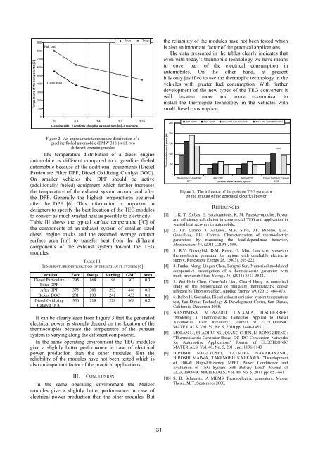
vehicles for forest fuels. Characteristic temperatures havebeen measured at different locations of the exhaust systemwhich is significantly differs from a common gasolineengine driven vehicle.The aim of this study is to present a comparison of theefficiency of different commercially available TEGmodules applying in the exhaust system of differentdiesel or gasoline engine automobile.Table II contains the studied thermoelectric modules.These modules are commercially available with modestprice. Table II shows the geometric dimension of theTEG modules, the maximum tested temperaturedifferences between the cold and hot side of the TEG, andthe produced maximum electrical power.TABLE II.THERMOELECTRIC MODULES OF THEM COMMERCIAL USE[1, 2, 3]Module name Dimensions ΔT [ o C] P max[W]TEC1-12707 40 mm x 40 mm 51 0.5TEC1-12708 40 mm x 40 mm 68 0.85Melcor HT9-3-25 25 mm x 25 mm 190 2.5Bi2Te3 N=3161 0.4Melcor HT6-12-40 Bi2Te340 mm x 40 mm 68 0.75II. TEMPERATURE DISTRIBUTION OF TYPICALEXHAUST SYSTEMSRecent progress in thermoelectric device technologyhas revealed the possibility of practical large-scale TEGsand various applications such as vehicles andmicroelectronic devices.This is especially interesting with the vehicles on dieseldrive like cars and boats. Application of the thermopiletechnology reduces overall diesel consumption. Byapplying the thermopile technology it is possible to coverenergy costs for eg light and computer systemsetc. This way it isn’t necessary to use the diesel generatorbecause dissipated thermo energy can be converted toelectricity.The four following potential sources are recoverable bya thermoelectric generator on a long-haul truck Dieselengine [7]:– Coolant water (between 90_C and 110_C);– Exhaust gases (between 250_C and 350_C, Fig. 1b);– Exhaust gas recirculation (EGR) gases (between 400_Cand 500_C, Fig. 1a);– Charge air cooler outlet gases (CAC) (usually around150_C).Exergy calculations show that the most energy can beextracted from exhaust gases. Despite the lower exhaustgas temperature (due to temperature loss in theturbocompressor) compared with the EGR temperature,exhaust gases exhibit a higher mass flow rate, whichincreases their exergy (available recovery).Figure 1 shows the structure of the Exhaust system inone diesel drive car, with marked points of the thermoenergy dissipation area like Diesel Oxidizing Catalyst,Diesel Particulate Filter and Exhaust Cooler.This construction allows effective application of thethermopile technology on larger surface.Thermoelectric generators utilizing as a source of heatthe exhaust gas from internal combustion enginesmounted in vehicles, primarily automobiles, are wellknown. It should be noted, however, that the requirementsimposed on such generators are rather complex anddiverse. They must be compact, lightweight, and able toendure heavy vibration during transport. Furthermore,thermoelectric generators for such applications mustoperate efficiently in different engine operating modes,which entails additional difficulties.The use of thermoelectric materials in vehicular enginesfor wasted heat recovery, can help considerably in theworld need for energy saving and reduction of pollutants.The allocated power and the temperatures that prevailin the exhaust pipe of an intermediate size car aresatisfactory enough for the efficient application of athermoelectric device. The most advisable place appearsto be precisely after the catalyst, where high temperaturesprevail. The output power and the efficiency of the devicedepend on the operational situation of the engine and onthe effective designing of the heat exchanger.Each TE element experiences a small temperaturedifference, so that greater surface area will improveperformance. As the system is fully scalable and modular,different layouts can be designed for specific needs suchas optimized electrical output, power density, and size.Heat pipes are one solution for carriage of heat to TEMs,providing a large heating area that can support manymodules.Figure 1. An approximate temperature distribution of agasoline fueled automobile (BMW 318i) with twodifferent operating modesThe temperature distribution of the exhaust system ofthe automobiles depends on the engine type. Anapproximate temperature distribution of a gasoline fueledautomobile (BMW 318i) with two different operatingmodes (full and a usual or averaged load) can be seen inFigure 2 from qualitative point of view the temperature ofthe exhaust system is monotonically decreasing along theexhaust pipe from the engine toward the tail of the pipe.30
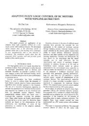
Temperature of the components [C]900800700600500400300200100Full loadUsual loadTminTmaxthe reliability of the modules have not been tested whichis also an important factor of the practical applications.The data presented in the tables clearly indicates thateven with today’s thermopile technology we have meansto cover part of the electrical consumption inautomobiles. On the other hand, at presentit is only justified to use the thermopile technology in thevehicles with greater fuel consumption. With furtherdevelopment of the new types of the TEG converters itwill became more and more economical toinstall the thermopile technology in the vehicles withsmall diesel consumption.00 0,6 1,4 2,3 3,35 rear side250TEC1-12707 TEC1-12708 Melcor HT9-3-25 Bi2Te3 N31 Melcor HT6-12-40 Bi2Te3 N31Figure 2. An approximate temperature distribution of agasoline fueled automobile (BMW 318i) with twodifferent operating modesThe temperature distribution of a diesel engineautomobile is different compared to a gasoline fueledautomobile because of the additional equipments (DieselParticulate Filter DPF, Diesel Oxidizing Catalyst DOC).On smaller vehicles the DPF should be active(additionally fueled) equipment which further increasesthe temperature of the exhaust system around and afterthe DPF. Generally the highest temperatures occurredafter the DPF [6]. This information is important todesigners to specify the best location of the TEG modulesto convert as much wasted heat as possible to electricity.Table III shows the typical surface temperature [ o C] ofthe components of an exhaust system of smaller sizeddiesel engine trucks and the assumed average contactsurface area [m 2 ] to transfer heat from the differentcomponents of the exhaust system toward the TEGmodules.TABLE III.TEMPERATURE DISTRIBUTION OF THE EXHAUST SYSTEM [6]Location Ford Dodge Sterling GMC AreaDiesel Particulate 295 168 196 307 0.3Filter DPFAfter DPF 375 300 293 446 0.1Before DOC 231 193 241 435 0.1Diesel OxidizingCatalyst DOC356 218 228 308 0.2It can be clearly seen from Figure 3 that the generatedelectrical power is strongly depend on the location of thethermocouples because the temperature of the exhaustsystem is varying along the different components.In the same operating environment the TEG modulesgive a slightly better performance in case of electricalpower production than the other modules. But thereliability of the modules have not been tested which isalso an important factor of the practical applications.III. CONCLUSIONIn the same operating environment the Melcormodules give a slightly better performance in case ofelectrical power production than the other modules. ButGenerated electrical power [W]200150100500Diesel Particulate FilterDPFAfter DPF Before DOC Diesel Oxidizing CatalystDOCLocation of the exhaust systemFigure 3. The influence of the position TEG generatoron the amount of the generated electrical powerREFERENCES[1] 1. K. T. Zorbas, E. Hatzikraniotis, K. M. Paraskevopoulos, Powerand efficiency calculation in commercial TEG and application inwasted heat recovery in automobile.[2] 2. J.P. Carmo, J. Antunes, M.F. Silva, J.F. Riberio, L.M.Goncalves, J.H. Correia, Characterization of thermoelectricgenerators by measuring the load-dependence behavior,Measurement 44, (2011), 2194-2199.[3] 3. R.Y. Nuwayhid, D.M. Rowe, G. Min, Low cost stove-topthermoelectric generator for regions with unreliable electricitysupply, Renewable Energy 28, (2003), 205-222.[4] 4. Fankai Meng, Lingen Chen, Fengrui Sun, Numerical model andcomparative investigation of a thermoelectric generator withmulti-irreversibilities, Energy, 36, (2011) 3513-3522.[5] 5. Wei-Hsin Chen, Chen-Yeh Liao, Chen-I Hung, A numericalstudy on the performance of miniature thermoelectric cooleraffected by Thomson effect, Applied Energy, 89, (<strong>2012</strong>) 464-473.[6] 6. Ralph H. Gonzales, Diesel exhaust emission system temperaturetest, San Dimas Technology & Development Center, San Dimas,California, December 2008.[7] N.ESPINOSA, M.LAZARD, L.AIXALA, H.SCHERRER:"Modeling a Thermoelectric Generator Applied to DieselAutomotive Heat Recovery" Journal of ELECTRONICMATERIALS, Vol. 39, No. 9, 2010 pp: 1446-1455[8] MOLAN LI, SHAOHUI XU, QIANG CHEN, LI-RONG ZHENG:"Thermoelectric-Generator-Based DC–DC Conversion Networksfor Automotive Applications" Journal of ELECTRONICMATERIALS, Vol. 40, No. 5, 2011, pp: 1136-1143[9] HIROSHI NAGAYOSHI, TATSUYA NAKABAYASHI,HIROSHI MAIWA, TAKENOBU KAJIKAWA: "Developmentof 100-W High-Efficiency MPPT Power Conditioner andEvaluation of TEG System with Battery Load" Journal ofELECTRONIC MATERIALS, Vol. 40, No. 5, 2011 pp: 657-661[10] S. B. Schaevitz, A MEMS Thermoelectric generators, MasterThesis, MIT, September 2000.31
- Page 1 and 2: 4 4 th IEEE International Symposium
- Page 3 and 4: EXPRES 20124 th International Sympo
- Page 5 and 6: Application of Thermopile Technolog
- Page 7 and 8: Design of a Solar Hybrid System....
- Page 9 and 10: ___________________________________
- Page 11 and 12: environmental protection and global
- Page 13 and 14: But can we use the human body sweat
- Page 15 and 16: IX. REFERENCES[1] Todorovic B. Cvje
- Page 17 and 18: QQ⎛ Λt⎞=⎜⎟⎝ Λ ⎠Nt Nwh
- Page 19 and 20: Analysis of the Energy-Optimum of H
- Page 21 and 22: V. OBJECTIVE FUNCTIONThe objective
- Page 23 and 24: The Set-Up Geometry of Sun Collecto
- Page 25 and 26: continuous east-west sun collector
- Page 27 and 28: continuously measure the thermal ch
- Page 29 and 30: CEvaluation of measurement resultsA
- Page 31: Application of Thermopile Technolog
- Page 35 and 36: nighttime, to weather or to the cha
- Page 37 and 38: η uη u0.50.40.30.20.1T 1 - 400K0.
- Page 39 and 40: Figure 10. . SPS Concept illustrati
- Page 41 and 42: [16] Zoya B. Popović: Wireless Pow
- Page 43 and 44: 25.0020.0015.0010.005.000.00Figure
- Page 45 and 46: · ℃ 0.0738 · 1.209 0.0892
- Page 47 and 48: use may be advantageous not only in
- Page 49 and 50: To find the reasons for this disagr
- Page 51 and 52: Toward Future: Positive Net-Energy
- Page 53 and 54: EnergyPlus environment, we used mod
- Page 55 and 56: To keep future energy consumption d
- Page 57 and 58: A New Calculation Method to Analyse
- Page 59 and 60: On Fig. 3. can be seen the areas th
- Page 61 and 62: Present and Future of Geothermal En
- Page 63 and 64: TABLE II.THE TEMPERATURE DATA AND C
- Page 65 and 66: Error in Water Meter Measuring at W
- Page 67 and 68: III.RESULTS OF MEASURMENTSEach meas
- Page 69 and 70: TABLE I.THE AVERAGE VALUE OF THERMA
- Page 71 and 72: If the walls of the DHEs are made o
- Page 73 and 74: Environmental External Costs Associ
- Page 75 and 76: iodiesel production facility with a
- Page 77 and 78: Contribution of unit processesto ex
- Page 79 and 80: Heat Pump News in HungaryBéla Ád
- Page 81 and 82: Thermal Comfort Measurements In Lar
- Page 83 and 84:
IV.DISCUSSIONThe sample frequencies
- Page 85 and 86:
For a Clear View of Traditional and
- Page 87 and 88:
esults in geographically distribute
- Page 89 and 90:
Design of a Solar Hybrid SystemMari
- Page 91 and 92:
Maintaining the set point temperatu
- Page 93 and 94:
Decision system theory model of ope
- Page 95 and 96:
parameter of pump in the function o
- Page 97 and 98:
Importance and Value of Predictive
- Page 99 and 100:
D. Overview of existing boiler oper
- Page 101 and 102:
HEAVY FUEL OIL FIRED, STEAMNATURAL
- Page 103 and 104:
MATHEMATICAL MODEL AND NUMERICAL SI
- Page 105 and 106:
C. Energy balance equationMathemati
- Page 107 and 108:
Discretization energy balance equat
- Page 109 and 110:
T ulf=32 º C, A - m =0.00162 kg/s,
- Page 111 and 112:
Comparison of Heat Pump and MicroCH
- Page 113 and 114:
the microCHP development. The energ
- Page 115 and 116:
control and stabilizer must be deve
- Page 117 and 118:
In Figure 1, in relation to the ord
- Page 119 and 120:
NPCC BHXOBYNI x1I x2I x3I x4LO YKYO
- Page 121 and 122:
exchange, as in reality, economies
- Page 123 and 124:
esponsibilities for consequences, o
- Page 125 and 126:
Coca-Cola Enterprise Inc had approx
- Page 127 and 128:
Flow Pattern Map for In Tube Evapor
- Page 129 and 130:
circumference with a liquid film. T
- Page 131 and 132:
Tube diameter: d 6 mm W Heat flux
- Page 133 and 134:
Realization of Concurrent Programmi
- Page 135 and 136:
applications the development, optim
- Page 137 and 138:
Renewable energy sources in automob
- Page 139 and 140:
commercial arrays can be built at b
- Page 141 and 142:
of multiple thin films produced usi
- Page 143:
EXPRES 20124 th International Sympo