Final Program EXPRES 2012 - Conferences
Final Program EXPRES 2012 - Conferences
Final Program EXPRES 2012 - Conferences
- No tags were found...

You also want an ePaper? Increase the reach of your titles
YUMPU automatically turns print PDFs into web optimized ePapers that Google loves.
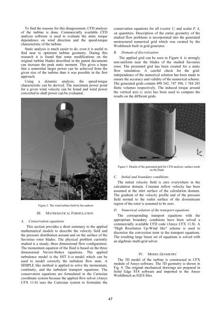
To find the reasons for this disagreement, CFD analysisof the turbine is done. Commercially available CFDanalysis software is used to evaluate the static torquedependence on wind direction and the speed-torquecharacteristic of the turbine.Static analysis is much easier to do, even it is useful tofind near to optimum turbine geometry. During thisresearch it is found that some modifications on theoriginal turbine blades described in the patent documentscan increase the peak static moment. This gives a hopethat a somewhat larger power can be achieved from thegiven size of the turbine than it was possible in the firstapproach.Using a dynamic analysis, the speed-torquecharacteristic can be derived. The maximum power pointfor a given wind velocity can be found and wind powerconverted to shaft power can be evaluated.conservation equations for all (vector U i and scalar P, k,) quantities. Description of the entire geometry of thestudied flow problems is incorporated into the generatedunstructured numerical grid which was created by theWorkbench built in grid generator.B. Domain of discretizationThe applied grid can be seen in Figure 4. is stronglynon-uniform near the blades of the studied Savoniusrotor. The presented grid has been created for a staticflow simulation. A careful check for the gridindependenceof the numerical solution has been made toensure the accuracy and validity of the numerical scheme.The generated grids contain 498 542, 747 398, 1 784 285finite volumes respectively. The induced torque aroundthe vertical axis (z axis) has been used to compare theresults on the different grids.Figure 3. Details of the generated grid for CFD analysis: surface meshon the bladeFigure 2. The wind turbine built by the authors.III.A. Conservation equationsMATHEMATICAL FORMULATIONThis section provides a short summary to the appliedmathematical models to describe the velocity field andthe pressure distribution around and on the surface of theSavonius rotor blades. The physical problem currentlystudied is a steady, three dimensional flow configuration.The momentum equation of the fluid is based on the threedimensional Navier-Stokes equations. The appliedturbulence model is the SST k- model which can beused to model correctly the turbulent flow state. ASIMPLE like method is applied to solve the momentum,continuity, and the turbulent transport equations. Theconservation equations are formulated in the Cartesiancoordinate system because the applied flow solver (AnsysCFX 11.0) uses the Cartesian system to formulate theC. Initial and boundary conditionsThe initial velocity field is zero everywhere in thecalculation domain. Constant inflow velocity has beenassumed at the inlet surface of the calculation domain.The gradient of the velocity profile and of the pressurefield normal to the outlet surface of the downstreamregion of the rotor is assumed to be zero.D. Numerical solution of the transport equationsThe corresponding transport equations with theappropriate boundary conditions have been solved acommercially available CFD code (Ansys CFX 11.0). A"High Resolution Up-Wind like" scheme is used todiscretize the convection term in the transport equations.The resulting large linear set of equations is solved withan algebraic multi-grid solver.IV.MODEL GEOMETRYThe 3D model of the turbine is constructed in CFXmodule of Ansys software. The 3D geometry is shown inFig. 4. The original mechanical drawings are prepared inSolid Edge ST4 software and imported to the AnsysWorkBench as IGES files.47