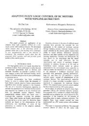
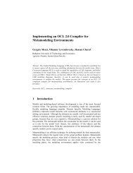
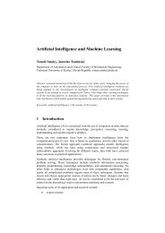
IV. MATERIALSDifferent materials display different efficiencies andhave different costs. Materials for efficient solar cellsmust have characteristics matched to the spectrum ofavailable light. Some cells are designed to efficientlyconvert wavelengths of solar light that reach the Earthsurface. However, some solar cells are optimized for lightabsorption beyond Earth's atmosphere as well. Lightabsorbing materials can often be used in multiple physicalconfigurations to take advantage of different lightabsorption and charge separation mechanisms.Materials presently used for photovoltaic solar cellsinclude monocrystalline silicon, polycrystalline silicon,amorphous silicon, cadmium telluride, and copper indiumselenide/sulfide.[16]“Picture 1.” The Shockley-Queisser limit for thetheoretical maximum efficiency of a solar cell.Semiconductors with band gap between 1 and 1.5eV, ornear-infrared light, have the greatest potential to form anefficient cell. (The efficiency "limit" shown here can beexceeded by multijunction solar cells.) Many currentlyavailable solar cells are made from bulk materials that arecut into wafers between 180 to 240 micrometers thick thatare then processed like other semiconductors.Other materials are made as thin-films layers, organicdyes, and organic polymers that are deposited onsupporting substrates. A third group are made fromnanocrystals and used as quantum dots (electron-confinednanoparticles). Silicon remains the only material that iswell-researched in both bulk and thin-film forms.Max. Efficiency (%)Bandgap (eV)Picture 1. Shockley - Queisser full curveA. Crystalline siliconBy far, the most prevalent bulk material for solar cellsis crystalline silicon (abbreviated as a group as c-Si), alsoknown as "solar grade silicon". Bulk silicon is separatedinto multiple categories according to crystallinity andcrystal size in the resulting ingot, ribbon, or wafer.“Picture 2.” show basic structure of a silicon basedsolar cell and its working mechanism.1) Monocrystalline silicon (c-Si)Often made using the Czochralski process. Singlecrystalwafer cells tend to be expensive, and because theyare cut from cylindrical ingots, do not completely cover asquare solar cell module without a substantial waste ofrefined silicon. Hence most c-Si panels have uncoveredgaps at the four corners of the cells.2) Polycrystalline silicon, or multicrystalline silicon,(poly-Si or mc-Si)Made from cast square ingots — large blocks of moltensilicon carefully cooled and solidified. Poly-Si cells areless expensive to produce than single crystal siliconHoleAluminiumAntireflection layerPicture 2. Basic structure of a silicon based solar cell and itsworking mechanism.cells,but are less efficient. United States Department ofEnergy data show that there were a higher number ofpolycrystalline sales than monocrystalline silicon sales.3) Ribbon siliconIs a type of polycrystalline silicon: it is formed bydrawing flat thin films from molten silicon and results in apolycrystalline structure. These cells have lowerefficiencies than poly-Si, but save on production costs dueto a great reduction in silicon waste, as this approach doesnot require sawing from ingots.[17]B. Thin filmsIn 2010 the market share of thin film declined by 30%as thin film technology was displaced by more efficientcrystalline silicon solar panels (the light and dark bluebars).Cadmium telluride (CdTe), copper indium galliumselenide (CIGS) and amorphous silicon (A-Si) are threethin-film technologies often used as outdoor photovoltaicsolar power production. CdTe technology is most costcompetitive among them.[18] CdTe technology costsabout 30% less than CIGS technology and 40% less thanA-Si technology in 2011.1) Cadmium telluride solar cellA cadmium telluride solar cell uses a cadmium telluride(CdTe) thin film, a semiconductor layer to absorb andconvert sunlight into electricity.The cadmium present inthe cells would be toxic if released. However, release isimpossible during normal operation of the cells and isunlikely during fires in residential roofs.[19] A squaremeter of CdTe contains approximately the same amountof Cd as a single C cell Nickel-cadmium battery, in amore stable and less soluble form.[19]2) Copper indium gallium selenideCopper indium gallium selenide (CIGS) is a direct bandgap material. It has the highest efficiency (~20%) amongthin film materials (see CIGS solar cell). Traditionalmethods of fabrication involve vacuum processesincluding co-evaporation and sputtering. Recentdevelopments at IBM and Nanosolar attempt to lower thecost by using non-vacuum solution processes.3) Gallium arsenide multijunctionHigh-efficiency multijunction cells were originallydeveloped for special applications such as satellites andspace exploration, but at present, their use in terrestrialconcentrators might be the lowest cost alternative in termsof $/kWh and $/W.[20] These multijunction cells consistSiO2138
of multiple thin films produced using metalorganic vapourphase epitaxy. A triple-junction cell, for example, mayconsist of the semiconductors: GaAs, Ge, and GaInP 2 .[21]Each type of semiconductor will have a characteristicband gap energy which, loosely speaking, causes it toabsorb light most efficiently at a certain color, or moreprecisely, to absorb electromagnetic radiation over aportion of the spectrum. The semiconductors are carefullychosen to absorb nearly all of the solar spectrum, thusgenerating electricity from as much of the solar energy aspossible.GaAs based multijunction devices are the most efficientsolar cells to date.Tandem solar cells based on monolithic, seriesconnected, gallium indium phosphide (GaInP), galliumarsenide GaAs, and germanium Ge p-n junctions, areseeing demand rapidly rise.4) Light-absorbing dyes (DSSC)Dye-sensitized solar cells (DSSCs) are made of lowcostmaterials and do not need elaborate equipment tomanufacture, so they can be made in a DIY fashion,possibly allowing players to produce more of this type ofsolar cell than others. In bulk it should be significantlyless expensive than older solid-state cell designs. DSSC'scan be engineered into flexible sheets, and although itsconversion efficiency is less than the best thin film cells,its price/performance ratio should be high enough to allowthem to compete with fossil fuel electrical generation. TheDSSC has been developed by Prof. Michael Grätzel in1991 at the Swiss Federal Institute of Technology (EPFL)in Lausanne (CH).Typically a ruthenium metalorganic dye (Ru-centered)is used as a monolayer of light-absorbing material. Thedye-sensitized solar cell depends on a mesoporous layer ofnanoparticulate titanium dioxide to greatly amplify thesurface area (200–300 m 2 /g TiO 2, as compared toapproximately 10 m 2 /g of flat single crystal). Thephotogenerated electrons from the light absorbing dye arepassed on to the n-type TiO 2, and the holes are absorbedby an electrolyte on the other side of the dye. The circuitis completed by a redox couple in the electrolyte, whichcan be liquid or solid. This type of cell allows a moreflexible use of materials, and is typically manufactured byscreen printing and/or use of Ultrasonic Nozzles, with thepotential for lower processing costs than those used forbulk solar cells. However, the dyes in these cells alsosuffer from degradation under heat and UV light, and thecell casing is difficult to seal due to the solvents used inassembly. In spite of the above, this is a popular emergingtechnology with some commercial impact forecast withinthis decade. The first commercial shipment of DSSC solarmodules occurred in July 2009 from G24i Innovations.[22]5) Organic/polymer solar cellsOrganic solar cells are a relatively novel technology,yet hold the promise of a substantial price reduction (overthin-film silicon) and a faster return on investment. Thesecells can be processed from solution, hence the possibilityof a simple roll-to-roll printing process, leading toinexpensive, large scale production.Organic solar cells and polymer solar cells are builtfrom thin films (typically 100 nm) of organicsemiconductors including polymers, such aspolyphenylene vinylene and small-molecule compoundslike copper phthalocyanine (a blue or green organicpigment) and carbon fullerenes and fullerene derivativessuch as PCBM. Energy conversion efficiencies achievedto date using conductive polymers are low compared toinorganic materials.In addition, these cells could be beneficial for someapplications where mechanical flexibility anddisposability are important.These devices differ from inorganic semiconductorsolar cells in that they do not rely on the large built-inelectric field of a PN junction to separate the electrons andholes created when photons are absorbed. The activeregion of an organic device consists of two materials, onewhich acts as an electron donor and the other as anacceptor. When a photon is converted into an electronhole pair, typically in the donor material, the charges tendto remain bound in the form of an exciton, and areseparated when the exciton diffuses to the donor-acceptorinterface. The short exciton diffusion lengths of mostpolymer systems tend to limit the efficiency of suchdevices. Nanostructured interfaces, sometimes in the formof bulk heterojunctions, can improve performance.[23]6) Silicon thin filmsSilicon thin-film cells are mainly deposited by chemicalvapor deposition (typically plasma-enhanced, PE-CVD)from silane gas and hydrogen gas. Depending on thedeposition parameters, this can yield:[24]a) Amorphous silicon (a-Si or a-Si:H)An amorphous silicon (a-Si) solar cell is made ofamorphous or microcrystalline silicon and its basicelectronic structure is the p-i-n junction. A-Si is attractiveas a solar cell material because it is abundant and nontoxic(unlike its CdTe counterpart) and requires a lowprocessing temperature, enabling production of devices tooccur on flexible and low-cost substrates. As theamorphous structure has a higher absorption rate of lightthan crystalline cells, the complete light spectrum can beabsorbed with a very thin layer of photo-electrically activematerial. A film only 1 micron thick can absorb 90% ofthe usable solar energy.[25]Amorphous silicon has a higher bandgap (1.7 eV) thancrystalline silicon (c-Si) (1.1 eV), which means it absorbsthe visible part of the solar spectrum more strongly thanthe infrared portion of the spectrum. As nc-Si has aboutthe same bandgap as c-Si, the nc-Si and a-Si canadvantageously be combined in thin layers, creating alayered cell called a tandem cell. The top cell in a-Siabsorbs the visible light and leaves the infrared part of thespectrum for the bottom cell in nc-Si.b) Protocrystalline silicon or Nanocrystallinesilicon (nc-Si or nc-Si:H), also called microcrystallinesilicon.It has been found that protocrystalline silicon with alow volume fraction of nanocrystalline silicon is optimalfor high open circuit voltage.[26] These types of siliconpresent dangling and twisted bonds, which results in deepdefects (energy levels in the bandgap) as well asdeformation of the valence and conduction bands (bandtails). The solar cells made from these materials tend tohave lower energy conversion efficiency than bulk silicon,but are also less expensive to produce. The quantumefficiency of thin film solar cells is also lower due to139
- Page 1 and 2:
4 4 th IEEE International Symposium
- Page 3 and 4:
EXPRES 20124 th International Sympo
- Page 5 and 6:
Application of Thermopile Technolog
- Page 7 and 8:
Design of a Solar Hybrid System....
- Page 9 and 10:
___________________________________
- Page 11 and 12:
environmental protection and global
- Page 13 and 14:
But can we use the human body sweat
- Page 15 and 16:
IX. REFERENCES[1] Todorovic B. Cvje
- Page 17 and 18:
QQ⎛ Λt⎞=⎜⎟⎝ Λ ⎠Nt Nwh
- Page 19 and 20:
Analysis of the Energy-Optimum of H
- Page 21 and 22:
V. OBJECTIVE FUNCTIONThe objective
- Page 23 and 24:
The Set-Up Geometry of Sun Collecto
- Page 25 and 26:
continuous east-west sun collector
- Page 27 and 28:
continuously measure the thermal ch
- Page 29 and 30:
CEvaluation of measurement resultsA
- Page 31 and 32:
Application of Thermopile Technolog
- Page 33 and 34:
Temperature of the components [C]90
- Page 35 and 36:
nighttime, to weather or to the cha
- Page 37 and 38:
η uη u0.50.40.30.20.1T 1 - 400K0.
- Page 39 and 40:
Figure 10. . SPS Concept illustrati
- Page 41 and 42:
[16] Zoya B. Popović: Wireless Pow
- Page 43 and 44:
25.0020.0015.0010.005.000.00Figure
- Page 45 and 46:
· ℃ 0.0738 · 1.209 0.0892
- Page 47 and 48:
use may be advantageous not only in
- Page 49 and 50:
To find the reasons for this disagr
- Page 51 and 52:
Toward Future: Positive Net-Energy
- Page 53 and 54:
EnergyPlus environment, we used mod
- Page 55 and 56:
To keep future energy consumption d
- Page 57 and 58:
A New Calculation Method to Analyse
- Page 59 and 60:
On Fig. 3. can be seen the areas th
- Page 61 and 62:
Present and Future of Geothermal En
- Page 63 and 64:
TABLE II.THE TEMPERATURE DATA AND C
- Page 65 and 66:
Error in Water Meter Measuring at W
- Page 67 and 68:
III.RESULTS OF MEASURMENTSEach meas
- Page 69 and 70:
TABLE I.THE AVERAGE VALUE OF THERMA
- Page 71 and 72:
If the walls of the DHEs are made o
- Page 73 and 74:
Environmental External Costs Associ
- Page 75 and 76:
iodiesel production facility with a
- Page 77 and 78:
Contribution of unit processesto ex
- Page 79 and 80:
Heat Pump News in HungaryBéla Ád
- Page 81 and 82:
Thermal Comfort Measurements In Lar
- Page 83 and 84:
IV.DISCUSSIONThe sample frequencies
- Page 85 and 86:
For a Clear View of Traditional and
- Page 87 and 88:
esults in geographically distribute
- Page 89 and 90: Design of a Solar Hybrid SystemMari
- Page 91 and 92: Maintaining the set point temperatu
- Page 93 and 94: Decision system theory model of ope
- Page 95 and 96: parameter of pump in the function o
- Page 97 and 98: Importance and Value of Predictive
- Page 99 and 100: D. Overview of existing boiler oper
- Page 101 and 102: HEAVY FUEL OIL FIRED, STEAMNATURAL
- Page 103 and 104: MATHEMATICAL MODEL AND NUMERICAL SI
- Page 105 and 106: C. Energy balance equationMathemati
- Page 107 and 108: Discretization energy balance equat
- Page 109 and 110: T ulf=32 º C, A - m =0.00162 kg/s,
- Page 111 and 112: Comparison of Heat Pump and MicroCH
- Page 113 and 114: the microCHP development. The energ
- Page 115 and 116: control and stabilizer must be deve
- Page 117 and 118: In Figure 1, in relation to the ord
- Page 119 and 120: NPCC BHXOBYNI x1I x2I x3I x4LO YKYO
- Page 121 and 122: exchange, as in reality, economies
- Page 123 and 124: esponsibilities for consequences, o
- Page 125 and 126: Coca-Cola Enterprise Inc had approx
- Page 127 and 128: Flow Pattern Map for In Tube Evapor
- Page 129 and 130: circumference with a liquid film. T
- Page 131 and 132: Tube diameter: d 6 mm W Heat flux
- Page 133 and 134: Realization of Concurrent Programmi
- Page 135 and 136: applications the development, optim
- Page 137 and 138: Renewable energy sources in automob
- Page 139: commercial arrays can be built at b
- Page 143: EXPRES 20124 th International Sympo