warning - Docs.hvacpartners.com
warning - Docs.hvacpartners.com
warning - Docs.hvacpartners.com
You also want an ePaper? Increase the reach of your titles
YUMPU automatically turns print PDFs into web optimized ePapers that Google loves.
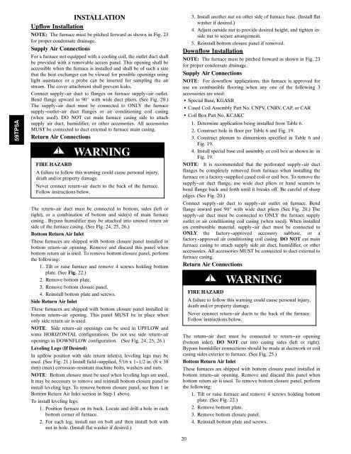
59TP5AINSTALLATIONUpflow InstallationNOTE: The furnace must be pitched forward as shown in Fig. 23for proper condensate drainage.Supply Air ConnectionsFor a furnace not equipped with a cooling coil, the outlet duct shallbe provided with a removable access panel. This opening shall beaccessible when the furnace is installed and shall be of such a sizethat the heat exchanger can be viewed for possible openings usinglight assistance or a probe can be inserted for sampling the airstream. The cover attachment shall prevent leaks.Connect supply -air duct to flanges on furnace supply -air outlet.Bend flange upward to 90_ with wide duct pliers. (See Fig. 20.)The supply -air duct must be connected to ONLY the furnacesupply -outlet-air duct flanges or air conditioning coil casing(when used). DO NOT cut main furnace casing side to attachsupply air duct, humidifier, or other accessories. All accessoriesMUST be connected to duct external to furnace main casing.Return Air Connections! WARNINGFIRE HAZARDA failure to follow this <strong>warning</strong> could cause personal injury,death and/or property damage.Never connect return -air ducts to the back of the furnace.Follow instructions below.The return -air duct must be connected to bottom, sides (left orright), or a <strong>com</strong>bination of bottom and side(s) of main furnacecasing.. Bypass humidifier may be attached into unused return airside of the furnace casing. (See Fig. 24, 25, 26.)Bottom Return Air InletThese furnaces are shipped with bottom closure panel installed inbottom return -air opening. Remove and discard this panel whenbottom return air is used. To remove bottom closure panel, performthe following:1. Tilt or raise furnace and remove 4 screws holding bottomplate. (See Fig. 22.)2. Remove bottom plate.3. Remove bottom closure panel.4. Reinstall bottom plate and screws.Side Return Air InletThese furnaces are shipped with bottom closure panel installed inbottom return -air opening. This panel MUST be in place whenonly side return air is used.NOTE: Side return -air openings can be used in UPFLOW andsome HORIZONTAL configurations. Do not use side return -airopenings in DOWNFLOW configuration. (See Fig. 24, 25, 26.)Leveling Legs (If Desired)In upflow position with side return inlet(s), leveling legs may beused. (See Fig. 21.) Install field -supplied, 5/16 x 1 -1/2 in. (8 x 38mm) (max) corrosion -resistant machine bolts, washers and nuts.NOTE: Bottom closure must be used when leveling legs are used.It may be necessary to remove and reinstall bottom closure panel toinstall leveling legs. To remove bottom closure panel, see Item 1 inBottom Return Air Inlet section in Step 1 above.To install leveling legs:1. Position furnace on its back. Locate and drill a hole in eachbottom corner of furnace.2. For each leg, install nut on bolt and then install bolt withnut in hole. (Install flat washer if desired.)3. Install another nut on other side of furnace base. (Install flatwasher if desired.)4. Adjust outside nut to provide desired height, and tighten insidenut to secure arrangement.5. Reinstall bottom closure panel if removed.Downflow InstallationNOTE: The furnace must be pitched forward as shown in Fig. 23for proper condensate drainage.Supply Air ConnectionsNOTE: For downflow applications, this furnace is approved foruse on <strong>com</strong>bustible flooring when any one of the following 3accessories are used:S Special Base, KGASBS Cased Coil Assembly Part No. CNPV, CNRV, CAP, or CARS Coil Box Part No. KCAKC1. Determine application being installed from Table 6.2. Construct hole in floor per Table 6 and Fig. 19.3. Construct plenum to dimensions specified in Table 6 andFig. 19.4. Install special base coil assembly or coil box as shown in inFig. 19.NOTE: It is re<strong>com</strong>mended that the perforated supply -air ductflanges be <strong>com</strong>pletely removed from furnace when installing thefurnace on a factory -supplied cased coil or coil box. To remove thesupply -air duct flange, use wide duct pliers or hand seamers tobend flange back and forth until it breaks off. Be careful of sharpedges. (See Fig. 20.)Connect supply -air duct to supply -air outlet on furnace. Bendflange inward past 90_ with wide duct pliers (See Fig. 20.) Thesupply -air duct must be connected to ONLY the furnace supplyoutlet or air conditioning coil casing (when used). When installedon <strong>com</strong>bustible material, supply -air duct must be connected toONLY the factory -approved accessory subbase, or afactory -approved air conditioning coil casing. DO NOT cut mainfurnace casing to attach supply side air duct, humidifier, or otheraccessories. All accessories MUST be connected to duct external tofurnace casing.Return Air Connections20! WARNINGFIRE HAZARDA failure to follow this <strong>warning</strong> could cause personal injury,death and/or property damage.Never connect return -air ducts to the back of the furnace.Follow instructions below.The return -air duct must be connected to return -air opening(bottom inlet). DO NOT cut into casing sides (left or right).Bypass humidifier connections should be made at ductwork or coilcasing sides exterior to furnace. (See Fig. 25.)Bottom Return Air InletThese furnaces are shipped with bottom closure panel installed inbottom return -air opening. Remove and discard this panel whenbottom return air is used. To remove bottom closure panel, performthe following:1. Tilt or raise furnace and remove 4 screws holding bottomplate. (See Fig. 22.)2. Remove bottom plate.3. Remove bottom closure panel.4. Reinstall bottom plate and screws.


