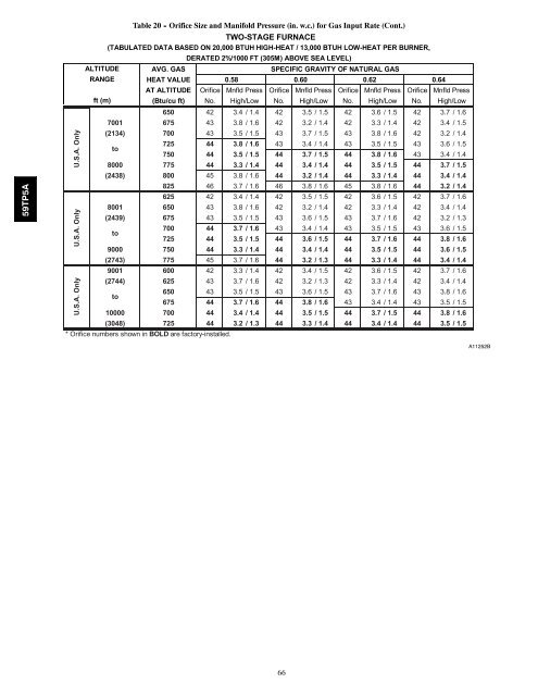
59TP5AALTITUDERANGEft (m)Table 20 - Orifice Size and Manifold Pressure (in. w.c.) for Gas Input Rate (Cont.)TWO-STAGE FURNACE(TABULATED DATA BASED ON 20,000 BTUH HIGH-HEAT / 13,000 BTUH LOW-HEAT PER BURNER,DERATED 2%/1000 FT (305M) ABOVE SEA LEVEL)AVG. GASSPECIFIC GRAVITY OF NATURAL GASHEAT VALUE 0.58 0.60 0.62 0.64AT ALTITUDE Orifice Mnfld Press Orifice Mnfld Press Orifice Mnfld Press Orifice Mnfld Press(Btu/cu ft) No. High/Low No. High/Low No. High/Low No. High/Low650 42 3.4 / 1.4 42 3.5 / 1.5 42 3.6 / 1.5 42 3.7 / 1.67001 675 43 3.8 / 1.6 42 3.2 / 1.4 42 3.3 / 1.4 42 3.4 / 1.5(2134) 700 43 3.5 / 1.5 43 3.7 / 1.5 43 3.8 / 1.6 42 3.2 / 1.4to725 44 3.8 / 1.6 43 3.4 / 1.4 43 3.5 / 1.5 43 3.6 / 1.5750 44 3.5 / 1.5 44 3.7 / 1.5 44 3.8 / 1.6 43 3.4 / 1.48000 775 44 3.3 / 1.4 44 3.4 / 1.4 44 3.5 / 1.5 44 3.7 / 1.5(2438) 800 45 3.8 / 1.6 44 3.2 / 1.4 44 3.3 / 1.4 44 3.4 / 1.4825 46 3.7 / 1.6 46 3.8 / 1.6 45 3.8 / 1.6 44 3.2 / 1.4625 42 3.4 / 1.4 42 3.5 / 1.5 42 3.6 / 1.5 42 3.7 / 1.68001 650 43 3.8 / 1.6 42 3.2 / 1.4 42 3.3 / 1.4 42 3.4 / 1.4(2439) 675 43 3.5 / 1.5 43 3.6 / 1.5 43 3.7 / 1.6 42 3.2 / 1.3to700 44 3.7 / 1.6 43 3.4 / 1.4 43 3.5 / 1.5 43 3.6 / 1.5725 44 3.5 / 1.5 44 3.6 / 1.5 44 3.7 / 1.6 44 3.8 / 1.69000 750 44 3.3 / 1.4 44 3.4 / 1.4 44 3.5 / 1.5 44 3.6 / 1.5(2743) 775 45 3.7 / 1.6 44 3.2 / 1.3 44 3.3 / 1.4 44 3.4 / 1.49001 600 42 3.3 / 1.4 42 3.4 / 1.5 42 3.6 / 1.5 42 3.7 / 1.6(2744) 625 43 3.7 / 1.6 42 3.2 / 1.3 42 3.3 / 1.4 42 3.4 / 1.4to650 43 3.5 / 1.5 43 3.6 / 1.5 43 3.7 / 1.6 43 3.8 / 1.6675 44 3.7 / 1.6 44 3.8 / 1.6 43 3.4 / 1.4 43 3.5 / 1.510000 700 44 3.4 / 1.4 44 3.5 / 1.5 44 3.7 / 1.5 44 3.8 / 1.6(3048) 725 44 3.2 / 1.3 44 3.3 / 1.4 44 3.4 / 1.4 44 3.5 / 1.5* Orifice numbers shown in BOLD are factory-installed.U.S.A. Only U.S.A. OnlyU.S.A. OnlyA11252B66
SERVICE AND MAINTENANCEPROCEDURES! WARNINGFIRE, INJURY OR DEATH HAZARDFailure to follow this <strong>warning</strong> could result in personalinjury, death and/or property damage.The ability to properly perform maintenance on thisequipment requires certain knowledge, mechanical skills,tools, and equipment. If you do not possess these, do notattempt to perform any service and maintenance on thisequipment other than those procedures re<strong>com</strong>mended in theOwner’s Manual.!CAUTIONENVIRONMENTAL HAZARDFailure to follow this caution may result in environmentalpollution.Remove and recycle all <strong>com</strong>ponents or materials (i.e. oil,refrigerant, control board, etc.) before unit final disposal.! WARNINGELECTRICAL SHOCK, FIRE OR EXPLOSIONHAZARDFailure to follow this <strong>warning</strong> could result in personalinjury or death, or property damage.Before installing, modifying, or servicing system, mainelectrical disconnect switch must be in the OFF position andinstall a lockout tag. There may be more than onedisconnect switch. Lock out and tag switch with a suitable<strong>warning</strong> label. Verify proper operation after servicing.!CAUTIONELECTRICAL OPERATION HAZARDFailure to follow this caution may result in improperfurnace operation or failure of furnace.Label all wires prior to disconnection when servicingcontrols. Wiring errors can cause improper and dangerousoperation.GeneralThese instructions are written as if the furnace is installed in anupflow application. An upflow furnace application is where theblower is located below the <strong>com</strong>bustion and controls section of thefurnace, and conditioned air is discharged upward. Since thisfurnace can be installed in any of the 4 positions shown in Fig. 2,you must revise your orientation to <strong>com</strong>ponent locationaccordingly.Electrical Controls and Wiring! WARNINGELECTRICAL SHOCK HAZARDFailure to follow this <strong>warning</strong> could result in personal injuryor death.There may be more than one electrical supply to the furnace.Check accessories and cooling unit for additional electricalsupplies that must be shut off during furnace servicing. Lockout and tag switch with a suitable <strong>warning</strong> label.The electrical ground and polarity for 115 -v wiring must beproperly maintained. Refer to Fig. 34 for field wiring informationand to Fig. 63 for furnace wiring information.NOTE: If the polarity is not correct, the STATUS LED on thecontrol will flash rapidly and prevent the furnace from heating. Thecontrol system also requires an earth ground for proper operationof the control and flame-sensing electrode.The 24 -v circuit contains an automotive -type, 3 -amp. fuse locatedon the control. (See Fig. 35.) Any shorts of the 24 -v wiring duringinstallation, service, or maintenance will cause this fuse to blow. Iffuse replacement is required, use ONLY a 3 -amp. fuse. The controlLED will display status code 24 when fuse needs to be replaced.TroubleshootingRefer to the service label. (See Fig. 54—Service Label.)The Troubleshooting Guide (See Fig. 62) can be a useful tool inisolating furnace operation problems. Beginning with the word“Start,” answer each question and follow the appropriate arrow tothe next item.The Guide will help to identify the problem or failed <strong>com</strong>ponent.After replacing any <strong>com</strong>ponent, verify correct operation sequence.Proper instrumentation is required to service electrical controls.The control in this furnace is equipped with a Status Code LED(Light -Emitting Diode) to aid in installation, servicing, andtroubleshooting. Status codes can be viewed at the indicator inblower door. The amber furnace control LED is either ONcontinuously, rapid flashing, or a code <strong>com</strong>posed of 2 digits. Thefirst digit is the number of short flashes, the second digit is thenumber of long flashes.For an explanation of status codes, refer to service label located onblower door or Fig. 54, and the troubleshooting guide which canbe obtained from your distributor.Retrieving Stored Fault CodesNOTE: Fault codes cannot be retrieved if a thermostat signal(24 -v on W, Y, G, etc.) is present, or if any delays such as bloweroff -delays are active. The stored status codes will NOT be erasedfrom the control memory when 115- or 24-v power is interrupted.See the Service Label (Fig. 54) for more information. The mostrecent fault code may be retrieved as follows:1. Leave 115-v power connected to furnace.2. Observe the status LED through the blower door (the lowerdoor on upflow applications) indicator. Refer to the ServiceLabel (Fig. 54) to interpret the LED.3. Remove the Main/Control door (the upper door on upflowinstallations).4. BRIEFLY disconnect and reconnect ONE of the main limitwires.5. The LED will flash the last stored fault code. Refer to theService Label (Fig. 54) to interpret the LED.6. Reinstall the Main/Control door.59TP5A67