

warning - Docs.hvacpartners.com
warning - Docs.hvacpartners.com
warning - Docs.hvacpartners.com

Create successful ePaper yourself
Turn your PDF publications into a flip-book with our unique Google optimized e-Paper software.
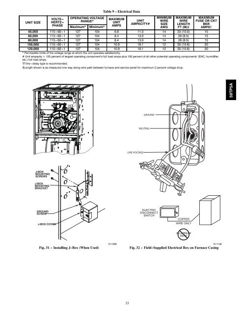
UNIT SIZEVOLTS ---HERTZ ---PHASEOPERATING VOLTAGERANGE*Maximum*Minimum*Table 9 – Electrical DataMAXIMUMUNITAMPSUNITAMPACITY#MINIMUMWIRESIZEAWGMAXIMUMWIRELENGTHFT (M)}MAXIMUMFUSE OR CKTBKRAMPS{40,000 115 --- 60 --- 1 127 104 6.8 11.0 14 33 (10.0) 1560,000 115 --- 60 --- 1 127 104 8.4 13.0 14 28 (8.5) 1580,000 115 --- 60 --- 1 127 104 8.4 13.0 14 28 (8.5) 15100,000 115 --- 60 --- 1 127 104 10.9 16.1 12 35 (10.6) 20120,000 115 --- 60 --- 1 127 104 10.9 16.1 12 35 (10.6) 20* Permissible limits of the voltage range at which the unit operates satisfactorily.# Unit ampacity = 125 percent of largest operating <strong>com</strong>ponent’s full load amps plus 100 percent of all other potential operating <strong>com</strong>ponents’ (EAC, humidifier,etc.) full load amps.{Time---delay type is re<strong>com</strong>mended.}Length shown is as measured one way along wire path between furnace and service panel for maximum 2 percent voltage drop.59TP5AGROUNDNEUTRALLINE VOLTAGEJ−BOXMOUNTINGSCREWSJ−BOXMOUNTINGBRACKETGROUNDSCREWJ−BOX COVERELECTRICDISCONNECTSWITCHCOPPERWIRE ONLYALUMINUMWIREFig. 31 - Installing J -Box (When Used)A11299A11146Fig. 32 - Field -Supplied Electrical Box on Furnace Casing33


