warning - Docs.hvacpartners.com
warning - Docs.hvacpartners.com
warning - Docs.hvacpartners.com
You also want an ePaper? Increase the reach of your titles
YUMPU automatically turns print PDFs into web optimized ePapers that Google loves.
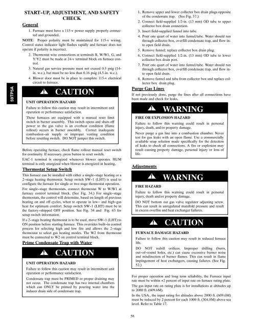
59TP5ASTART -UP, ADJUSTMENT, AND SAFETYCHECKGeneral1. Furnace must have a 115-v power supply properly connectedand grounded.NOTE: Proper polarity must be maintained for 115-v wiring.Control status indicator light flashes rapidly and furnace does notoperate if polarity is incorrect.2. Thermostat wire connections at terminals R, W/W1, G, andY/Y2 must be made at 24-v terminal block on furnace control.3. Natural gas service pressure must not exceed 0.5 psig (14-in. w.c.), but must be no less than 0.16 psig (4.5-in. w.c.).4. Blower door must be in place to <strong>com</strong>plete 115-v electricalcircuit to furnace.!CAUTIONUNIT OPERATION HAZARDFailure to follow this caution may result in intermittent unitoperation or performance satisfaction.These furnaces are equipped with a manual reset limitswitch in burner assembly. This switch opens and shuts offpower to the gas valve is an overheat condition (flamerollout) occurs in burner assembly. Correct inadequate<strong>com</strong>bustion -air supply or improper venting conditionbefore resetting switch. DO NOT jumper this switch.Before operating furnace, check flame rollout manual reset switchfor continuity. If necessary, press button to reset switch.EAC-1 terminal is energized whenever blower operates. HUMterminal is only energized when blower is energized in heating.Thermostat Setup SwitchThis furnace can be installed with either a single -stage heating or a2 -stage heating thermostat. Setup switch SW -1 (LHT) is used toconfigure the furnace for single or two stage thermostat operation.For single -stage thermostats, connect thermostat W to W/W1 atfurnace control terminal block. (See Fig. 34.) For single-stagethermostats, the control will determine, based on length of previousheating on and off cycles, when to operate in low - and high -gasheat for optimum <strong>com</strong>fort. Setup switch SW -1 (LHT) must be inthe factory -shipped OFF position. See Fig. 34 andFig. 63 forsetup switch information.If a 2 -stage heating thermostat is to be used, move SW-1 (LHT) toON position before starting furnace. This overrides built -in controlprocess for selecting high and low fire and allows the 2 -stagethermostat to select gas heating modes. The W2 from thermostatmust be connected to W2 on control terminal block.Prime Condensate Trap with Water!CAUTIONUNIT OPERATION HAZARDFailure to follow this caution may result in intermittent unitoperation or performance satisfaction.Condensate trap must be PRIMED or proper draining maynot occur. The condensate trap has two internal chamberswhich can ONLY be primed by pouring water into theinducer drain side of condensate trap.1. Remove upper and lower collector box drain plugs oppositeof the condensate trap. (See Fig. 57.)2. Connect field-supplied 1/2-in. (13 mm) OD tube to uppercollector box drain connection.3. Insert field-supplied funnel into tube.4. Pour one quart of water into funnel/tube. Water should runthrough collector box, overfill condensate trap, and flow intoopen field drain.5. Remove funnel; replace collector box drain plug.6. Connect field-supplied 1/2-in. (13 mm) OD tube to lowercollector box drain port.7. Pour one quart of water into funnel/tube. Water should runthrough collector box, overfill condensate trap, and flow intoopen field drain.8. Remove funnel and tube from collector box and replace collectorbox drain plug.Purge Gas LinesIf not previously done, purge the lines after all connections havebeen made and check for leaks.! WARNINGFIRE OR EXPLOSION HAZARDFailure to follow this <strong>warning</strong> could result in personalinjury, death, and/or property damage.Never purge a gas line into a <strong>com</strong>bustion chamber. Nevertest for gas leaks with an open flame. Use a <strong>com</strong>merciallyavailable soap solution made specifically for the detectionof leaks to check all connections. A fire or explosion mayresult causing property damage, personal injury or loss oflife.Adjustments! WARNINGFIRE HAZARDFailure to follow this <strong>warning</strong> could result in personalinjury, death and/or property damage.DO NOT bottom out gas valve regulator adjusting screw.This can result in unregulated manifold pressure and resultin excess overfire and heat exchanger failures.!CAUTIONFURNACE DAMAGE HAZARDFailure to follow this caution may result in reduced furnacelife.DO NOT redrill orifices. Improper drilling (burrs,out-of-round holes, etc.) can cause excessive burner noiseand misdirection of burner flames. This can result in flameimpingement of heat exchangers, causing failures. (See Fig.52.)For proper operation and long term reliability, the Furnace inputrate must be within +2 percent of input rate on furnace rating plate.The gas input rate on rating plate is for installations at altitudes upto 2000 ft. (609.6M).In the USA., the input rating for altitudes above 2000 ft. (609.6M)must be reduced by 2 percent for each 1000 ft. (304.8M) above sealevel. Refer to Table 17.58


