59TP5AItem Clearance Description Canadian Installation (1) U.S. Installation (2)Clearance above grade, veranda, porch, deck, balconyor anticipated snowA12 in. (305 mm). 18 in. (457 mm) above roof surface. 12 in. (305 mm)levelBCDEFGHClearance to a window or door that may be openedI Clearance to service regulator vent outlet 3ft.(.9M)JClearance to non---mechanical air supply inlet tobuilding or the <strong>com</strong>bustion air inlet to any other appliance6 in. (152 mm) for appliances 10,000 Btuh (3kW),and 100,000 Btuh (30 kW)For clearances not specified in ANSI Z223.1/NFPA 54or CSA B149.1, clearances shall be in accordancewith local installation codes and the requirements ofthe gas supplier and the manufacturer’s installationinstructions.3ft.(.9M)within15ft. (4.6 M) abovethemeter/regulator assembly6 in. (152 mm) for appliances 10,000 Btuh (3kW),and 100,000 Btuh (30 kW)K Clearance to a mechanical air supply inlet 6ft.(1.8M) 3ft.(.9M)LClearance under a veranda, porch, deck, or balcony12 in. (305 mm). Permitted only if veranda, porch,deck, or balcony is fully open on a minimum of twosides beneath the floor.MClearance to each side of the centerline extendedabove or below vent terminal of the furnace to a dryeror water heater vent, or other appliance’s direct vent12 in. (305 mm) 12 in. (305 mm)intake or exhaustNClearance to the vent terminal of a dryer vent, waterheater vent, or other appliances direct vent intake or 3ft.(.9M)3ft.(.9M)exhaustO Clearance from a plumbing vent stack 3ft.(.9M) 3ft.(.9M)PClearance above paved sidewalk or paved drivewaylocated on public property7 ft. (2.1 M). A vent shall not terminate above a sidewalkor paved driveway that is located between twosingle family dwellings and serves both dwellings.4 ft. (1.2 M) below or to the side of the opening. 1 ft.(.3 M) above the opening.For clearances not specified in ANSI Z223.1/NFPA 54or CSA B149.1, clearances shall be in accordancewith local installation codes and the requirements ofthe gas supplier and the manufacturer’s installationinstructions.Clearance to a permanently closed windowVertical clearance to a ventilated soffit located abovethe terminal within a horizontal distance of 2 feet (61cm) from the centerline of the terminalClearance to an unventilated soffitClearance to an outside cornerClearance to an inside cornerClearance to each side of the centerline extendedabove electrical meter or gas service regulator assembly3ft.(.9M)within15ft.(4.6M)abovethemeter/regulatorassembly.* 3 ft. (.9 M) * For clearances not specified in ANSIZ223.1/NFPA54 orCSAB149.1,clearancesshallbeinaccordance with local installation codes and therequirements of the gas supplier and the manufacturer’sinstallation instructions.4 ft. (1.2 M) below or to the side of the opening. 1 ft.(.3 M) above the opening.For clearances not specified in ANSI Z223.1/NFPA 54or CSA B149.1, clearances shall be in accordancewith local installation codes and the requirements ofthe gas supplier and the manufacturer’s installationinstructions.7ft.(2.1M).(1) In accordance with the current CSA B149.1, Natural Gas and Propane Installation Code.(2) In accordance with the current ANSI Z223.1.NFPA 54, National Fuel Gas CodeNotes:1. The vent for this appliance shall not terminate:a. Over public walkways; orb. Near soffit vents of crawl space vents or other areas where condensate or vapor could create a nuisance or hazard or property damage; orc. Where condensate vapor could cause damage or could be detrimental to the operation of regulators, relief valves, or other equipment.2. When locating vent terminations, consideration must be given to prevailing winds, location, and other conditions which may cause recirculation of the <strong>com</strong>bustion products of adjacent vents.Recirculation can cause poor <strong>com</strong>bustion, inlet condensate problems, and accelerated corrosion of the heat exchangers.3. Avoid venting under a deck or large overhang. Recirculation could occur and cause performance or system problems.Fig. 46 - Ventilated Combustion Air and Non -Direct Vent Termination ClearanceA1104754
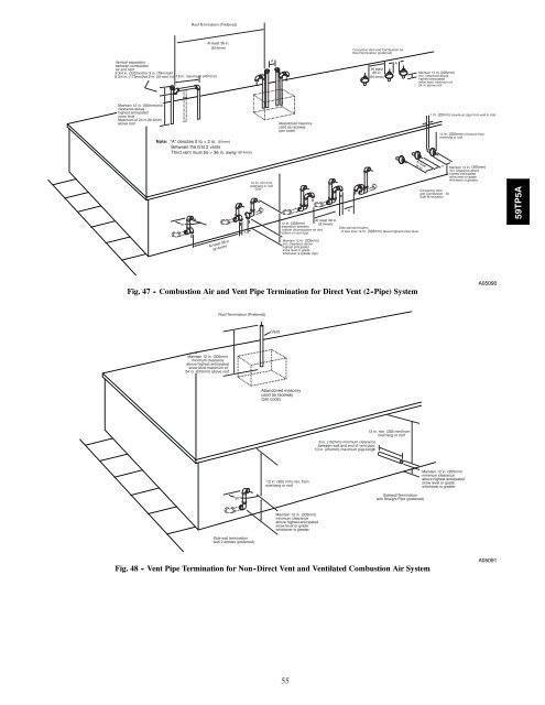
Roof T e rm ination (Pref erred)At least 36 in.(914mm)Concent ri c V ent and Comb ustion Ai rRoof T er mination (pre fe rred)V e r tical separationbetween <strong>com</strong>b ustionair and v ent8 3/4 in. (222mm)f or 3 in. (76mm)ki t6 3/4 in. (172mm)f or 2 in. (51mm) ki t 18 in. maximu m (457mm)AAt least36 in.(914mm)AMaintain 12 in. (305mm)min. clearance abo vehighest anticipatedsno w le ve l, maximum of24 in . abo v e roofMaintain 12 in. (305mm)min.clearance abo vehighest anticipatedsno w le ve lMaximum of 24 in.(614mm)abo v e roofNote: "A" denotes 0 to < 2 in. (51mm)Between the first 2 ventsThird vent must be > 36 in. away (914mm)Abandoned masonr yused as race wa y(per code)1 in. (25mm) maximum (typ) from wall to inlet12 in. (305mm) minimum fro mov erhang or roof90 °A12 in. min fro mov erhang or roof(typ)12 in. (305mm)separation betweenbottom of<strong>com</strong>b ustion air andbottom of v ent (typ)AA t le a s t3 6 in .At least 36 in.(914mm)Side wa ll te rm inatio nof less than 12 in. (305mm) above highest snow levelAConcent ri c V entand Comb ustion - AirSide T e rm inatio nMaintain 12 in. (305mm)min. clearance ab ov ehighest anticipatedsno w le v el or gradewhich eve r is greate r59TP5AA t least 36 in .(914mm)Maintain 12 in. (305mm)min. clearance abo vehighest anticipatedsno w le ve l or gradewhiche ve r is greater (typ)Fig. 47 - Combustion Air and Vent Pipe Termination for Direct Vent (2 -Pipe) SystemA05090Roof Termination (Preferred)VentMaintain 12 in (305mm) .minimum clearanceabove highest anticipatedsnow level maximum of24 in. (610mm) above . roofAbandoned masonryused as raceway(per code)6 in. (152mm) minimum clearancebetween wall and end of vent pipe.10 in. (254mm) maximum pipe length12 in. min. (305 mm)fromoverhang or roof12 in. (305 mm) min. fromoverhang or roofMaintain 12 in. (305mm)minimum clearanceabove highest anticipatedsnow level or gradewhichever is greater90°Sidewall Terminationwith Straight Pipe (preferred)Maintain 12 in. (305mm)minimum clearanceabove highest anticipatedsnow level or gradewhichever is greater.Side wall terminationwith 2 elbows (preferred)Fig. 48 - Vent Pipe Termination for Non -Direct Vent and Ventilated Combustion Air SystemA0509155