warning - Docs.hvacpartners.com
warning - Docs.hvacpartners.com
warning - Docs.hvacpartners.com
You also want an ePaper? Increase the reach of your titles
YUMPU automatically turns print PDFs into web optimized ePapers that Google loves.
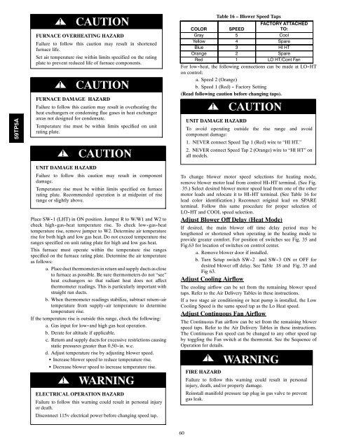
59TP5A!CAUTIONFURNACE OVERHEATING HAZARDFailure to follow this caution may result in shortenedfurnace life.Set air temperature rise within limits specified on the ratingplate to prevent reduced life of furnace <strong>com</strong>ponents.!CAUTIONFURNACE DAMAGE HAZARDFailure to follow this caution may result in overheating theheat exchangers or condensing flue gases in heat exchangerareas not designed for condensate.Temperature rise must be within limits specified on unitrating plate.!CAUTIONUNIT DAMAGE HAZARDFailure to follow this caution may result in <strong>com</strong>ponentdamage.Temperature rise must be within limits specified on furnacerating plate. Re<strong>com</strong>mended operation is at midpoint of riserange or slightly above.Place SW -1 (LHT) in ON position. Jumper R to W/W1 and W2 tocheck high -gas -heat temperature rise. To check low -gas -heattemperature rise, remove jumper to W2. Determine air temperaturerise for both high and low gas heat. Do not exceed temperature riseranges specified on unit rating plate for high and low gas heat.This furnace must operate within the temperature rise rangesspecified on the furnace rating plate. Determine the air temperatureas follows:a. Placeduct thermometersin return and supply ducts ascloseto furnace as possible. Be sure thermometers do not “see”heat exchangers so that radiant heat does not affectthermometer readings. This is particularly important withstraight run ducts.b. When thermometer readings stabilize, subtract return -airtemperature from supply -air temperature to determinetemperature rise.If the temperature rise is outside this range, check the following:a. Gas input for low -and high gas heat operation.b. Derate for altitude if applicable.c. Return and supply ducts for excessive restrictions causingstatic pressures greater than 0.50 -in. w.c.d. Adjust temperature rise by adjusting blower speed.S Increase blower speed to reduce temperature rise.S Decrease blower speed to increase temperature rise.! WARNINGELECTRICAL OPERATION HAZARDFailure to follow this <strong>warning</strong> could result in personal injuryor death.Disconnect 115v electrical power before changing speed tap.Table 16 – Blower Speed TapsFACTORY ATTACHEDCOLOR SPEEDTO:Gray 5 CoolYellow 4 SpareBlue 3 HI HTOrange 2 SpareRed 1 LO HT/Cont FanFor low -heat, the following connections can be made at LO -HTon control:a. Speed 2 (Orange)b. Speed 1 (Red) - Factory Setting(Read following caution before changing taps).!CAUTIONUNIT DAMAGE HAZARDTo avoid operating outside the rise range and avoid<strong>com</strong>ponent damage:1. NEVER connect Speed Tap 1 (Red) wire to “HI HT.”2. NEVER connect Speed Tap 2 (Orange) wire to “HI HT” onall models.To change blower motor speed selections for heating mode,remove blower motor lead from control HI-HT terminal. (See Fig.35.) Select desired blower motor speed lead from one of the othermotor leads and relocate it to HI -HT terminal. (See Table 16 forlead color identification.) Reconnect original lead on SPAREterminal. Follow this same procedure for proper selection ofLO -HT and COOL speed selection.Adjust Blower Off Delay (Heat Mode)If desired, the main blower off time delay period may belengthened or shortened when operating in the heating mode toprovide greater <strong>com</strong>fort. For position of switches see Fig. 35 andFig.63 for location of switches on control center.a. Remove blower door if installed.b. Turn Setup switch SW-2 and SW-3 ON or OFF fordesired blower off delay. See Table 18 and Fig. 35 andFig 63.Adjust Cooling AirflowThe cooling airflow can be set from the remaining blower speedtaps. Refer to the Air Delivery Tables in these instructions.If a two stage air conditioning or heat pump is installed, the LowCooling Speed is the same speed tap as the Lo Heat speed.Adjust Continuous Fan AirflowThe Continuous Fan airflow can be set from the remaining blowerspeed taps. Refer to the Air Delivery Tables in these instructions.The Continuous Fan speed can be changed to any other speed tapby toggling the Fan switch at the thermostat. See the Sequence ofOperation for details.! WARNINGFIRE HAZARDFailure to follow this <strong>warning</strong> could result in personalinjury, death, and/or property damage.Reinstall manifold pressure tap plug in gas valve to preventgas leak.60


