warning - Docs.hvacpartners.com
warning - Docs.hvacpartners.com
warning - Docs.hvacpartners.com
Create successful ePaper yourself
Turn your PDF publications into a flip-book with our unique Google optimized e-Paper software.
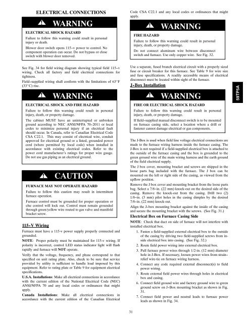
ELECTRICAL CONNECTIONS! WARNINGELECTRICAL SHOCK HAZARDFailure to follow this <strong>warning</strong> could result in personalinjury or death.Blower door switch opens 115 -v power to control. No<strong>com</strong>ponent operation can occur. Do not bypass or closeswitch with blower door removed.Code CSA C22.1 and any local codes or ordinances that mightapply.! WARNINGFIRE HAZARDFailure to follow this <strong>warning</strong> could result in personalinjury, death, or property damage.Do not connect aluminum wire between disconnectswitch and furnace. Use only copper wire. See Fig. 32.See Fig. 34 for field wiring diagram showing typical field 115 -vwiring. Check all factory and field electrical connections fortightness.Field -supplied wiring shall conform with the limitations of 63_F(33_C) rise.! WARNINGELECTRICAL SHOCK AND FIRE HAZARDFailure to follow this <strong>warning</strong> could result in personalinjury, death, or property damage.The cabinet MUST have an uninterrupted or unbrokenground according to NEC ANSI/NFPA 70 -2011 or localcodes to minimize personal injury if an electrical faultshould occur. In Canada, refer to Canadian Electrical CodeCSA C22.1. This may consist of electrical wire, conduitapproved for electrical ground or a listed, grounded powercord (where permitted by local code) when installed inaccordance with existing electrical codes. Refer to thepower cord manufacturer’s ratings for proper wire gauge.Do not use gas piping as an electrical ground.!CAUTIONFURNACE MAY NOT OPERATE HAZARDFailure to follow this caution may result in intermittentfurnace operation.Furnace control must be grounded for proper operation orelse control will lock out. Control must remain groundedthrough green/yellow wire routed to gas valve and manifoldbracket screw.115 -V WiringFurnace must have a 115-v power supply properly connected andgrounded.NOTE: Proper polarity must be maintained for 115-v wiring. Ifpolarity is incorrect, control LED status indicator light will flashrapidly and furnace will NOT operate.Verify that the voltage, frequency, and phase correspond to thatspecified on unit rating plate. Also, check to be sure that serviceprovided by utility is sufficient to handle load imposed by thisequipment. Refer to rating plate or Table 9 for equipment electricalspecifications.U.S.A. Installations: Make all electrical connections in accordancewith the current edition of the National Electrical Code (NEC)ANSI/NFPA 70 and any local codes or ordinances that mightapply.Canada Installations: Make all electrical connections inaccordance with the current edition of the Canadian ElectricalUse a separate, fused branch electrical circuit with a properly sizedfuse or circuit breaker for this furnace. See Table 9 for wire sizeand fuse specifications. A readily accessible means of electricaldisconnect must be located within sight of the furnace.J-Box Installation! WARNINGFIRE OR ELECTRICAL SHOCK HAZARDFailure to follow this <strong>warning</strong> could result in personalinjury, death, or property damage.If field -supplied manual disconnect switch is to be mountedon furnace casing side, select a location where a drill orfastener cannot damage electrical or gas <strong>com</strong>ponents.The J-Box is used when field line voltage electrical connections aremade to the furnace wiring harness inside the furnace casing. TheJ-Box is not required if a field-supplied electrical box is attached tothe outside of the furnace casing and the box is grounded to thegreen ground wire of the main wiring harness and the earth groundof the field electrical supply.The J box cover, mounting bracket and screws are shipped in theloose parts bag included with the furnace. The J box can bemounted on the left or right side of the casing, as viewed from theupflow position.Remove the J box cover and mounting bracket from the loose partsbag. Select a 7/8 -in. (22 mm) knock-out on the desired side of thecasing. Remove the knock-out from the casing. Drill two (2)1/8 -in. (3 mm) pilot holes in the casing dimples by the desired7/8 -in. (22 mm) knock-out.Align the J-box mounting bracket against the inside of the casingand secure the mounting bracket with the screws. (See Fig. 31.)Electrical Box on Furnace Casing SideNOTE: Check that duct on side of furnace will not interfere withinstalled electrical box.1. Fasten a field-supplied external electrical box to the outsideof the casing by driving two field-supplied screws from insideelectrical box into casing. (See Fig. 32.)2. Route field power wiring into external electrical box.3. Pull furnace power wires through 1/2-in. (12 mm) diameterhole in J-Box. If necessary, loosen power wires from strain -relief wire-tie on furnace wiring harness.4. Connect any code required external disconnect(s) to fieldpower wiring.5. Route external field power wires through holes in electricalbox and casing.6. Connect field ground wire and factory ground wire to greenground screw on J-Box mounting bracket as shown in Fig.31.7. Connect field power and neutral leads to furnace powerleads as shown in Fig. 34.59TP5A31


