warning - Docs.hvacpartners.com
warning - Docs.hvacpartners.com
warning - Docs.hvacpartners.com
You also want an ePaper? Increase the reach of your titles
YUMPU automatically turns print PDFs into web optimized ePapers that Google loves.
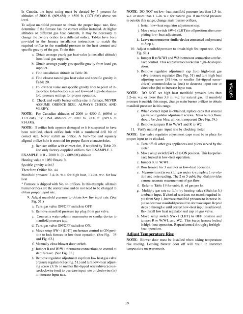
In Canada, the input rating must be derated by 5 percent foraltitudes of 2000 ft. (609.6M) to 4500 ft. (1371.6M) above sealevel.To adjust manifold pressure to obtain the proper input rate, first,determine if the furnace has the correct orifice installed. At higheraltitudes or different gas heat contents, it may be necessary tochange the factory orifice to a different orifice. Tables have beenprovided in the furnace installation instructions to match therequired orifice to the manifold pressure to the heat content andspecific gravity of the gas. To do this:a. Obtain average yearly gas heat value (at installed altitude)from local gas supplier.b. Obtain average yearly gas specific gravity from local gassupplier.c. Find installation altitude in Table 20.d. Find closest natural gas heat value and specific gravity inTable 20.e. Follow heat value and specific gravity lines to point of intersectionto find orifice size and low -and high -heat manifoldpressure settings for proper operation.f. Check and verify burner orifice size in furnace. NEVERASSUME ORIFICE SIZE. ALWAYS CHECK ANDVERIFY.NOTE: For Canadian altitudes of 2000 to 4500 ft. (609.6 to1371.6M), use USA altitudes of 2001 to 3000 ft. (609.6 to914.4M).NOTE: If orifice hole appears damaged or it is suspected to havebeen redrilled, check orifice hole with a numbered drill bit ofcorrect size. Never redrill an orifice. A burr -free and squarelyaligned orifice hole is essential for proper flame characteristics.g. Replace orifice with correct size, if required by Table 20.Use only factory -supplied orifices. See EXAMPLE 1.EXAMPLE 1: 0 - 2000 ft. (0 - 609.6M) altitudeHeating value = 1050 Btu/cu ft.Specific gravity = 0.62Therefore: Orifice No. 44Manifold pressure: 3.4 -in. w.c. for high heat, 1.4 -in. w.c. for lowheat* Furnace is shipped with No. 44 orifices. In this example, all mainburner orifices are the correct size and do not need to be changed toobtain proper input rate.9. Adjust manifold pressure to obtain low fire input rate. (SeeFig. 51.)a. Turn gas valve ON/OFF switch to OFF.b. Remove manifold pressure tap plug from gas valve.c. Connect a water column manometer or similar device tomanifold pressure tap.d. Turn gas valve ON/OFF switch to ON.e. Move setup SW-1 (LHT) on furnace control to ON positionto lock furnace in low -heat operation. (See Fig. 35and Fig. 63.)f. Manually close blower door switch.g. Jumper R and W/W1 thermostat connections on control tostart furnace. (See Fig. 35.)h. Remove regulator adjustment cap from low heat gas valvepressure regulator (See Fig. 51.) and turn low -heat adjustingscrew (3/16 or smaller flat-tipped screwdriver) counterclockwise(out) to decrease input rate or clockwise (in)to increase input rate.NOTE: DO NOT set low -heat manifold pressure less than 1.3 -in.w.c. or more than 1.7 -in. w.c. for natural gas. If manifold pressureis outside this range, change main burner orifices.i. Install low -heat regulator adjustment cap.j. Move setup switch SW -1 (LHT) to off position after <strong>com</strong>pletinglow -heat adjustment.k. Leave manometer or similar device connected and proceedto Step 4.10. Adjust manifold pressure to obtain high fire input rate. (SeeFig. 51.)a. Jumper R to W/W1 and W2 thermostat connections on furnacecontrol. This keeps furnace locked in high -heat operation.b. Remove regulator adjustment cap from high -heat gasvalve pressure regulator (See Fig. 51) and turn high heatadjusting screw (3/16 -in. or smaller flat -tipped screwdriver)counterclockwise (out) to decrease input rate orclockwise (in) to increase input rate.NOTE: DO NOT set high -heat manifold pressure less than3.2 -in. w.c. or more than 3.8 in. w.c. for natural gas. If manifoldpressure is outside this range, change main burner orifices to obtainmanifold pressure in this range.c. When correct input is obtained, replace caps that concealgas valve regulator adjustment screws. Main burner flameshould be clear blue, almost transparent (See Fig. 59.)d. Remove jumpers R to W/W1 and R to W2.11. Verify natural gas input rate by clocking meter.NOTE: Gas valve regulator adjustment caps must be in place forproper input to be clocked.a. Turn off all other gas appliances and pilots served by themeter.b. Move setup switch SW1 -2 to ON position. This keepsfurnacelocked in low -heat operation.c. Jumper R to W/W1.d. Run furnace for 3 minutes in low -heat operation.e. Measure time (in sec) for gas meter to <strong>com</strong>plete 1 revolutionand note reading. The 2 or 5 cubic feet dial providesa more accurate measurement of gas flow.f. Refer to Table 19 for cubic ft. of gas per hr.g. Multiply gas rate cu ft./hr by heating value (Btuh/cu ft.)to obtain input. If clocked rate does not match required inputfrom Step 1, increase manifold pressure to increase inputor decrease manifold pressure to decrease input.Repeatsteps b through e until correct low -heat input is achieved.Re -install low heat regulator seal cap on gas valve.h. Move setup switch SW -1 (LHT) to OFF position andjumper R to W/W1, and W2. This keeps furnace lockedin high -heat operation. Repeat items d through g forhigh -heat operation.Adjust Temperature RiseNOTE: Blower door must be installed when taking temperaturerise reading. Leaving blower door off will result in incorrecttemperature measurements.59TP5A59


