warning - Docs.hvacpartners.com
warning - Docs.hvacpartners.com
warning - Docs.hvacpartners.com
You also want an ePaper? Increase the reach of your titles
YUMPU automatically turns print PDFs into web optimized ePapers that Google loves.
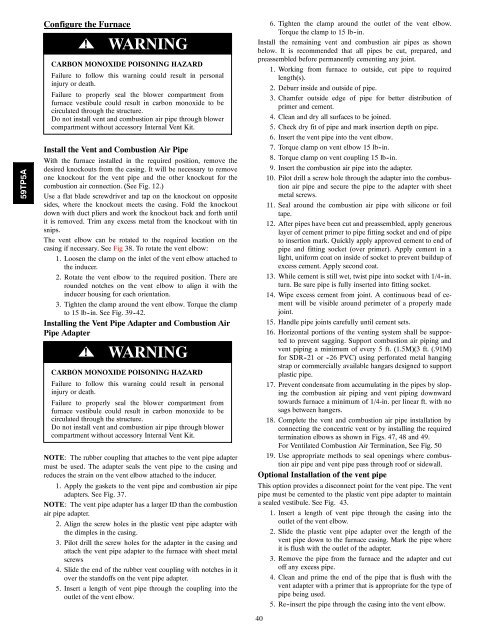
59TP5AConfigure the Furnace!WARNINGCARBON MONOXIDE POISONING HAZARDFailure to follow this <strong>warning</strong> could result in personalinjury or death.Failure to properly seal the blower <strong>com</strong>partment fromfurnace vestibule could result in carbon monoxide to becirculated through the structure.Do not install vent and <strong>com</strong>bustion air pipe through blower<strong>com</strong>partment without accessory Internal Vent Kit.Install the Vent and Combustion Air PipeWith the furnace installed in the required position, remove thedesired knockouts from the casing. It will be necessary to removeone knockout for the vent pipe and the other knockout for the<strong>com</strong>bustion air connection. (See Fig. 12.)Use a flat blade screwdriver and tap on the knockout on oppositesides, where the knockout meets the casing. Fold the knockoutdown with duct pliers and work the knockout back and forth untilit is removed. Trim any excess metal from the knockout with tinsnips.The vent elbow can be rotated to the required location on thecasing if necessary. See Fig 38. To rotate the vent elbow:1. Loosen the clamp on the inlet of the vent elbow attached tothe inducer.2. Rotate the vent elbow to the required position. There arerounded notches on the vent elbow to align it with theinducer housing for each orientation.3. Tighten the clamp around the vent elbow. Torque the clampto 15 lb -in. See Fig. 39 -42.Installing the Vent Pipe Adapter and Combustion AirPipe Adapter!WARNINGCARBON MONOXIDE POISONING HAZARDFailure to follow this <strong>warning</strong> could result in personalinjury or death.Failure to properly seal the blower <strong>com</strong>partment fromfurnace vestibule could result in carbon monoxide to becirculated through the structure.Do not install vent and <strong>com</strong>bustion air pipe through blower<strong>com</strong>partment without accessory Internal Vent Kit.NOTE: The rubber coupling that attaches to the vent pipe adaptermust be used. The adapter seals the vent pipe to the casing andreduces the strain on the vent elbow attached to the inducer.1. Apply the gaskets to the vent pipe and <strong>com</strong>bustion air pipeadapters. See Fig. 37.NOTE: The vent pipe adapter has a larger ID than the <strong>com</strong>bustionair pipe adapter.2. Align the screw holes in the plastic vent pipe adapter withthe dimples in the casing.3. Pilot drill the screw holes for the adapter in the casing andattach the vent pipe adapter to the furnace with sheet metalscrews4. Slide the end of the rubber vent coupling with notches in itover the standoffs on the vent pipe adapter.5. Insert a length of vent pipe through the coupling into theoutlet of the vent elbow.6. Tighten the clamp around the outlet of the vent elbow.Torque the clamp to 15 lb -in.Install the remaining vent and <strong>com</strong>bustion air pipes as shownbelow. It is re<strong>com</strong>mended that all pipes be cut, prepared, andpreassembled before permanently cementing any joint.1. Working from furnace to outside, cut pipe to requiredlength(s).2. Deburr inside and outside of pipe.3. Chamfer outside edge of pipe for better distribution ofprimer and cement.4. Clean and dry all surfaces to be joined.5. Check dry fit of pipe and mark insertion depth on pipe.6. Insert the vent pipe into the vent elbow.7. Torque clamp on vent elbow 15 lb -in.8. Torque clamp on vent coupling 15 lb -in.9. Insert the <strong>com</strong>bustion air pipe into the adapter.10. Pilot drill a screw hole through the adapter into the <strong>com</strong>bustionair pipe and secure the pipe to the adapter with sheetmetal screws.11. Seal around the <strong>com</strong>bustion air pipe with silicone or foiltape.12. After pipes have been cut and preassembled, apply generouslayer of cement primer to pipe fitting socket and end of pipeto insertion mark. Quickly apply approved cement to end ofpipe and fitting socket (over primer). Apply cement in alight, uniform coat on inside of socket to prevent buildup ofexcess cement. Apply second coat.13. While cement is still wet, twist pipe into socket with 1/4 -in.turn. Be sure pipe is fully inserted into fitting socket.14. Wipe excess cement from joint. A continuous bead of cementwill be visible around perimeter of a properly madejoint.15. Handle pipe joints carefully until cement sets.16. Horizontal portions of the venting system shall be supportedto prevent sagging. Support <strong>com</strong>bustion air piping andvent piping a minimum of every 5 ft. (1.5M)(3 ft. (.91M)for SDR -21 or -26 PVC) using perforated metal hangingstrap or <strong>com</strong>mercially available hangars designed to supportplastic pipe.17. Prevent condensate from accumulating in the pipes by slopingthe <strong>com</strong>bustion air piping and vent piping downwardtowards furnace a minimum of 1/4-in. per linear ft. with nosags between hangers.18. Complete the vent and <strong>com</strong>bustion air pipe installation byconnecting the concentric vent or by installing the requiredtermination elbows as shown in Figs. 47, 48 and 49.For Ventilated Combustion Air Termination, See Fig. 5019. Use appropriate methods to seal openings where <strong>com</strong>bustionair pipe and vent pipe pass through roof or sidewall.Optional Installation of the vent pipeThis option provides a disconnect point for the vent pipe. The ventpipe must be cemented to the plastic vent pipe adapter to maintaina sealed vestibule. See Fig. 43.1. Insert a length of vent pipe through the casing into theoutlet of the vent elbow.2. Slide the plastic vent pipe adapter over the length of thevent pipe down to the furnace casing. Mark the pipe whereit is flush with the outlet of the adapter.3. Remove the pipe from the furnace and the adapter and cutoff any excess pipe.4. Clean and prime the end of the pipe that is flush with thevent adapter with a primer that is appropriate for the type ofpipe being used.5. Re-insert the pipe through the casing into the vent elbow.40


