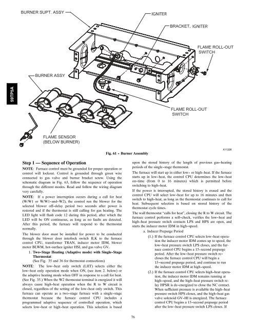
IGNITERIGNITERFLAME ROLL-OUTSWITCH59TP5AFLAME ROLL-OUTSWITCHFLAME SENSOR(BELOW BURNER)Fig. 61 - Burner AssemblyA11226Step 1 — Sequence of OperationNOTE: Furnace control must be grounded for proper operation orcontrol will lockout. Control is grounded through green wireconnected to gas valve and burner bracket screw. Using theschematic diagram in Fig. 63, follow the sequence of operationthrough the different modes. Read and follow the wiring diagramvery carefully.NOTE: If a power interruption occurs during a call for heat(W/W1 or W/W1 -and -W2), the control run the blower for theselected blower off-delay period two seconds after power isrestored and if the thermostat is still calling for gas heating. TheLED light will flash code 12 during this period, after which theLED will be ON continuous, as long as no faults are detected.After this period, the furnace will respond to the thermostatnormally.The blower door must be installed for power to be conductedthrough the blower door interlock switch ILK to the furnacecontrol CPU, transformer TRAN, inducer motor IDM, blowermotor BLWM, hot-surface igniter HSI, and gas valve GV..1. Two -Stage Heating (Adaptive mode) with Single-StageThermostat(See Fig. 35 and 36 for thermostat connections)NOTE: The low -heat only switch (LHT) selects either thelow -heat only operation mode when ON, (see item 2. below) orthe adaptive heating mode when OFF in response to a call for heat.(See Fig. 35.) When the W2 thermostat terminal is energized it willalways cause high -heat operation when the R to W circuit isclosed, regardless of the setting of the low -heat only switch. Thisfurnace can operate as a two -stage furnace with a single -stagethermostat because the furnace control CPU includes aprogrammed adaptive sequence of controlled operation, whichselects low -heat or high -heat operation. This selection is basedupon the stored history of the length of previous gas-heatingperiods of the single-stage thermostat.The furnace will start up in either low - or high -heat. If the furnacestarts up in low -heat, the control CPU determines the low -heaton -time (from 0 to 16 minutes) which is permitted beforeswitching to high -heat.If the power is interrupted, the stored history is erased and thecontrol CPU will select low -heat for up to 16 minutes and thenswitch to high -heat, as long as the thermostat continues to call forheat. Subsequent selection is based on stored history of thethermostat cycle times.The wall thermostat “calls for heat”, closing the R to W circuit. Thefurnace control performs a self -check, verifies the low -heat andhigh -heat pressure switch contacts LPS and HPS are open, andstarts the inducer motor IDM in high -speed.a. Inducer Prepurge Period(1.) If the furnace control CPU selects low -heat operationthe inducer motor IDM <strong>com</strong>es up to speed, thelow -heat pressure switch LPS closes, and the furnacecontrol CPU begins a 15 -second prepurgeperiod. After the low -heat pressure switch reclosesthe furnace control CPU will begin a15 -second prepurge period, and continue to runthe inducer motor IDM at high -speed.(2.) If the furnace control CPU selects high -heat operation,the inducer motor IDM remains running athigh -speed, and the high -heat pressure switch relayHPSR is de -energized to close the NC contact.When sufficient pressure is available the high -heatpressure switch HPS closes, and the high -heat gasvalve solenoid GV -HI is energized. The furnacecontrol CPU begins a 15 -second prepurge periodafter the low -heat pressure switch LPS closes. If76
the high -heat pressure switch HPS fails to closeand the low -heat pressure switch LPS closes, thefurnace will operate at low -heat gas flow rate untilthe high -heat pressure switch closes for a maximumof 2 minutes after ignition.b. Igniter Warm -Up -At the end of the prepurge period, the(Hot Surface Igniter) HSI is energized for a 17 -second igniterwarm -up period.c. Trial-for-Ignition Sequence-When the igniter warm -upperiod is <strong>com</strong>pleted the main gas valve relay contactsGVR -1 and -2 close to energize the gas valve solenoidGV -M, the gas valve opens, and 24 vac power is suppliedfor a field -installed humidifier at the HUM terminal. Thegas valve solenoid GV -M permits gas flow to the burnerswhere it is ignited by the HSI. Five sec after the GVRcloses, a 2 -sec flame proving period begins. The HSI igniterwill remain energized until the flame is sensed or untilthe 2 -sec flame proving period begins. If the furnace controlCPU selects high -heat operation, the high -heat gasvalve solenoid GV -HI is also energized.d. Flame-Proving -When the burner flame is proved at theflame-proving sensor electrode FSE, the inducer motorIDM switches to low -speed unless running at high -speed,and the furnace control CPU begins the blower-ON delayperiod and continues to hold the gas valve GV -M open.If the burner flame is not proved within two seconds, thecontrol CPU will close the gas valve GV -M, and the controlCPU will repeat the ignition sequence for up to threemore Trials -For -Ignition before going to Ignition - Lockout.Lockout will be reset automatically after three hours,by momentarily interrupting 115 vac power to the furnace,or by interrupting 24 vac power at SEC1 or SEC2 to thefurnace control CPU (not at W/W1, G, R, etc.). If flame isproved when flame should not be present, the furnace controlCPU will lock out of Gas-Heating mode and operatethe inducer motor IDM on high speed until flame is nolonger proved.e. Blower-ON Delay -If the burner flame is proven theblower -ON delay for low -heat and high -heat are as follows:Low -Heat-45 seconds after the gas valve GV -M is energizedthe blower motor (BLWM) is energized at LO HEATspeed.High -Heat-25 seconds after the gas valve GV -M is energizedthe BLWM is energized at HI HEAT speed. Simultaneously,the electronic air cleaner (EAC -1) terminal isenergized and remains energized as long as the BLWM isenergized.f. Switching from Low -to High -Heat-If the furnace controlCPU switches from low -heat to high -heat, the furnacecontrol CPU will switch the inducer motor IDM speedfrom low to high. The high -heat pressure switch relayHPSR is de-energized to closethe NC contact. When sufficientpressure is available the high -heat pressure switchHPS closes, and the high -heat gas valve solenoid GV -HIis energized. The blower motor BLWM will switch to HIHEAT speed five seconds after the furnace control CPUswitches from low -heat to high -heat.g. Switching from High - to Low -Heat -The furnace controlCPU will not switch from high -heat to low -heat whilethe thermostat R -to -W circuit is closed when using asingle stage thermostat.h. Blower -OFF Delay -When the thermostat is satisfied, theR to W circuit is opened, de-energizing the gas valve GV -M, stopping gas flow to the burners, and de-energizing thehumidifier terminal HUM. The inducer motor IDM will remainenergized for a 15 -second post-purge period. Theblower motor BLWM and air cleaner terminal EAC -1 willremain energized for 90, 120, 150, or 180 seconds (dependingon selection at blower-OFF delay switches). Thefurnace control CPU is factory -set for a 120 -secondblower -OFF delay.2. Two -Stage Thermostat and Two -Stage Heating (SeeFig. 35 and 36 for thermostat connections)NOTE: In this mode the LHT must be ON to select the low -heatonly operation mode in response to closing the thermostatR-to-W1 circuit. Closing the thermostat R-to-W1-and-W2circuits always causes high -heat operation, regardless of the settingof the low -heat-only switch.The wall thermostat “calls for heat”, closing the R -to -W1 circuitfor low -heat or closing the R -to -W1 and -W2 circuits forhigh -heat. The furnace control performs a self -check, verifies thelow -heat and high -heat pressure switch contacts LPS and HPS areopen, and starts the inducer motor IDM in high -speed.The start up and shut down functions and delays described in item1. above apply to the 2 -stage heating mode as well, except forswitching from low - to high -heat and vice versa.a. Switching from Low - to High -Heat-If the thermostatR -to - W1 circuit is closed and the R -to -W2 circuit closes,the furnace control CPU will switch the inducer motorIDM speed from low to high. The high -heat pressureswitch relay HPSR is de -energized to close the NC contact.When sufficient pressure is available the high -heat pressureswitch HPS closes, and the high -heat gas valve solenoidGV -HI is energized. The blower motor BLWM willswitch to HI HEAT speed five seconds after the R -to -W2circuit closes.b. Switching from High - to Low -Heat -If the thermostatR -to -W2 circuit opens, and the R -to -W1 circuit remainsclosed, the furnace control CPU will switch the inducermotor IDM speed from high to low. The high -heat pressureswitch relay HPSR is energized to open the NC contactand de-energize the high -heat gas valve solenoid GV -HI.When the inducer motor IDM reduces pressure sufficiently,the high -heat pressure switch HPS will open. Thegas valve solenoid GV -M will remain energized as longas the low -heat pressure switch LPS remains closed. Theblower motor BLWM will switch to LO HEAT speed fiveseconds after the R -to -W2 circuit opens.3. Cooling Mode-The thermostat “calls for cooling.”a. Single-Speed Cooling -(See Fig. 35 and 36 for thermostat connections)The thermostat closes the R -to -G -and -Y circuits. TheR -to - Y circuit starts the outdoor unit, and the R -to -G -and -Y/Y2 circuits start the furnace blower motorBLWM on COOL speed.The electronic air cleaner terminal EAC -1 is energizedwith 115 vac when the blower motor BLWM is operating.77When the thermostat is satisfied, the R -to -G and -Y circuitsare opened. The outdoor unit will stop, and the furnaceblower motor BLWM will continue operating on theCOOL speed for an additional 90 seconds. Jumper Y/Y2to DHUM to reduce the cooling off-delay to 5 seconds.(See Fig. 35.)b. Single-Stage Thermostat and Two -Speed Cooling(Adaptive Mode)(See Fig. 35 and 36 for thermostat connections)This furnace can operate a two -speed cooling unit with asingle -stage thermostat because the furnace control CPUincludes a programmed adaptive sequence of controlledoperation, which selects low -cooling or high -cooling operation.This selection is based upon the stored history ofthe length of previous cooling period of the single-stagethermostat.59TP5A