59TP5A78NOTE: The air conditioning relay disable jumper ACRDJ mustbe connected to enable the adaptive cooling mode in response to acall for cooling. (See Fig. 35.) When ACRDJ is in place, thefurnace control CPU can turn on the air conditioning relay ACR toenergize the Y/Y2 terminal and switch the outdoor unit tohigh -cooling.The furnace control CPU can start up the cooling unit in eitherlow - or high -cooling. If starting up in low -cooling, the furnacecontrol CPU determines the low -cooling on -time (from 0 to 20minutes) which is permitted before switching to high -cooling. Ifthe power is interrupted, the stored history is erased and the furnacecontrol CPU will select low -cooling for up to 20 minutes and thenenergize the air conditioning relay ACR to energize the Y/Y2terminal and switch the outdoor unit to high -cooling, as long asthe thermostat continues to call for cooling. Subsequent selection isbased on stored history of the thermostat cycle times. The wallthermostat “calls for cooling”, closing the R -to -G -and -Y circuits.The R -to -Y1 circuit starts the outdoor unit on low -cooling speed,and the R -to -G -and -Y1 circuits starts the furnace blower motorBLWM at low -cool speed (same speed as LO HEAT).If the furnace control CPU switches from low -cooling tohigh -cooling, the furnace control CPU will energize the airconditioning relay ACR. When the air conditioning relay ACR isenergized the R -to -Y1 -and -Y2 circuits switch the outdoor unit tohigh -cooling speed, and the R -to -G -and -Y1 -and -Y/Y2 circuitsswitch the furnace blower motor BLWM to COOL speed.NOTE: When transitioning from low -cooling to high -cooling theoutdoor unit <strong>com</strong>pressor will shut down for 1 minute while theBLWM continues to run at low -cool speed (same speed asLO -HEAT) until the outdoor unit <strong>com</strong>pressor <strong>com</strong>es back on athigh speed.The electronic air cleaner terminal EAC -1 is energized with 115vac whenever the blower motor BLWM is operating. When thethermostat is satisfied, the R -to -G -and -Y circuit are opened. Theoutdoor unit stops, and the furnace blower BLWM and electronicair cleaner terminal EAC -1 will remain energized for an additional90 seconds. Jumper Y1 to DHUM to reduce the cooling off-delayto 5 seconds. (See Fig. 35 .)c. Two -Stage Thermostat and Two -Speed Cooling (See Fig.35 and 36 for thermostat connections)NOTE: The air conditioning relay disable jumper ACRDJ mustbe disconnected to allow thermostat control of the outdoor unitstaging. (See Fig. 35.)The thermostat closes the R -to -G -and -Y1 circuits forlow-cooling or closes the R-to-G-and-Y1-and-Y2 circuits forhigh -cooling. The R -to -Y1 circuit starts the outdoor unit onlow -cooling speed, and the R -to -G -and -Y1 circuit starts thefurnace blower motor BLWM on low -cool speed (same speed asLO HEAT). The R -to -Y1 -and -Y2 circuits start the outdoor uniton high -cooling speed, and the R -to -G -and - Y/Y2 circuits startthe furnace blower motor BLWM on COOL speed. The electronicair cleaner terminal EAC -1 is energized with 115 vac whenever theblower motor BLWM is operating. When the thermostat issatisfied , th e R - to - G - an d - Y1 o r R - to - G - an d - Y1 - an d - Y2circuits are opened. The outdoor unit stops, and the furnace blowerBLWM and electronic air cleaner terminal EAC -1 will remainenergized for an additional 90 seconds. Jumper Y1 to DHUM toreduce the cooling off-delay to 5 seconds. (See Fig. 35.)4. Dehumidification Mode(See Fig. 35 and 36 for Thermidistat connections)The dehumidification output, D or DHUM on the Thermidistatshould be connected to the furnace control thermostatterminal DHUM. The dehumidification output, D orDHUM from a thermostat.When there is a dehumidify demand,the DHUM input is activated, which means 24 vacsignal is removed from the DHUM input terminal. In otherwords, the DHUM input logic is reversed. The DHUM inputis turned ON when no dehumidify demand exists. Once24 vac is detected by the furnace control on the DHUM input,the furnace control dehumidification capability is activated.If the DHUM input is low for more than 48 hours, thefurnace control reverts back to non -Thermidistat mode.The cooling operation described in item 3. above also appliesto operation with a dehumidification thermostat.. Theexceptions are listed below:a. Low cooling - When the R -to -G -and -Y1 circuit is closedand there is a demand for dehumidification,the furnaceblower motor BLWM will continue running at low -coolspeed (same speed as LO HEAT).b. High cooling - When the R -to -G -and -Y/Y2 circuit isclosed and there is a demand for dehumidification,the furnaceblower motor BLWM will drop the blower speedfrom COOL to HI HEAT for a maximum of 10 minutesbefore reverting back to COOL speed. If there is still a demandfor dehumidification after 20 minutes, the furnacecontrol CPU will drop the blower speed back to HI HEATspeed. This alternating 10 -minute cycle will continue aslong as there is a call for cooling.c. Cooling off -delay - When the “call for cooling” is satisfiedand there is a demand for dehumidification, the coolingblower-off delay is decreased from 90 seconds to 5seconds.5. Continuous Blower ModeWhen the R -to -G circuit is closed by the thermostat, theblower motor BLWM will operate on continuous-blowerspeed (can be set to LO HEAT, HI HEAT, or COOL speed).Factory default is LO HEAT speed. Terminal EAC -1 is energizedas long as the blower motor BLWM is energized.During a call for heat, the blower BLWM will stop duringigniter warm -up (17 seconds), ignition (7 seconds), andblower-ON delay (45 seconds in low -heat, and 25 secondsin high -heat), allowing the furnace heat exchangers to heatup more quickly, then restarts at the end of the blower-ONdelay period at LO HEAT or HI HEAT speed respectively.The blower motor BLWM will revert to continuous-blowerspeed after the heating cycle is <strong>com</strong>pleted. In high -heat, thefurnace control CPU will hold the blower motor BLWM atHI HEAT speed during the selected blower -OFF delay periodbefore reverting to continuous-blower speed.When the thermostat “calls for low -cooling”, the blowermotor BLWM will switch to operate at low -cool speed(same speed as LO HEAT). When the thermostat is satisfied,the blower motor BLWM will operate an additional 90seconds on low -cool speed before reverting back to continuous-blowerspeed.When the thermostat “calls for high -cooling”, the blowermotor BLWM will operate at COOL speed. When the thermostatis satisfied, the blower motor BLWM will operate anadditional 90 seconds on COOL speed before revertingback to continuous-blower speed.When the R -to -G circuit is opened, the blower motorBLWM will continue operating for an additional 5 seconds,if no other function requires blower motor BLWM operation.Continuous Blower Speed Selection from Thermostat Toselect different continuous-blower speeds from the roomthermostat, momentarily turn off the FAN switch or pushbutton on the room thermostat for 1 -3 seconds after theblower motor BLWM is operating. The furnace controlCPU will shift the continuous-blower speed from the factorysetting of LO HEAT to HI HEAT speed. Momentarilyturning off the FAN switch again at the thermostat will shiftthe continuous-blower speed from HI HEAT to COOL.Repeating the procedure will shift the continuous-blowerspeed from COOL to LO HEAT speed. The selection can bechanged as many times as desired and is stored in the
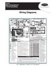
memory to be automatically used following a power interruption.NOTE: If the blower-off delay is set to the maximum, theadjustable continuous-fan feature is locked (i.e., fan speed cannotbe changed from its current setting).6. Heat Pump(See Fig. 35 and 36 for thermostat connections)When installed with a heat pump, the furnace control automaticallychanges the timing sequence to avoid long bloweroff times during demand defrost cycles. When the R -to -W/W1 - an d - Y1 o r R - to - W/W1 - an d - Y1 - an d - G circu itsare energized the furnace control CPU will switch to or turnon the blower motor BLWM at low -cool speed (same speedas LO HEAT), and begin a low -heat cycle. The blower motorBLWM will remain on until the end of the prepurgeperiod, then shut off for 24 seconds then <strong>com</strong>e back on atLO HEAT speed. When the W/W1 input signal disappears,the furnace control begins a normal inducer post-purgeperiod and the blower remains running at LO HEAT speed.If the R -to - W/W1 -and -Y1 -and -G signals disappear atthe same time, the blower motor BLWM will remain on forthe selected blower - OFF delay period. If the R -to -W/W1 -and -Y1 signals disappear, leaving the G signal, theblower motor BLWM will remain on for the selectedblower-OFF delay period then switch to continuousblowerspeed.When the R -to -W/W1 -and -Y/Y2, R -to -W/W1 -and -Y/Y2 - an d - G, R - to - W/W1 - an d - Y1 - an d - Y/Y2 , o r R - to -W/W1 -and - Y1 -and -Y/Y2 -and -G circuits are energizedthe furnace control CPU will switch to or turn on the blowermotor BLWM at COOL speed, and begin a high -heat cycle.The blower motor BLWM will remain on until the end ofthe prepurge period, then shut off for 24 seconds then <strong>com</strong>eback on at HI HEAT speed. When the W/W1 input signaldisappears, the furnace control begins a normal inducerpost-purge period and theblower switches to COOL speed after a 3 second delay. Ifth e R - to - W/W1 - an d - Y/Y2 - an d - G o r R - to - W/W1 - an d-Y1 -and - Y/Y2 -and -G signals disappear at the same time,the blower motor BLWM will remain on for the selectedblower-OFF delay period. If the R -to -W/W1 -an d - Y/Y2 o r R - to - W/W1 - an d - Y1 - an d - Y/Y2 sig n alsdisappear, leaving the G signal, the blower motor BLWMwill remain on for the selected blower- OFF delay periodthen switch to continuous-blower speed.Step 2 — Wiring DiagramsRefer to wiring diagram, Fig. 63.Step 3 — TroubleshootingRefer to the service label. (See Fig. 54—Service Label.) TheTroubleshooting Guide (see Fig. 62) can be a useful tool inisolating furnace operation problems. Beginning with the word“Start,” answer each question and follow the appropriate arrow tothe next item.The Guide will help to identify the problem or failed <strong>com</strong>ponent.After replacing any <strong>com</strong>ponent, verify correct operation sequence.59TP5A79


