Watlow Series 922 User's Manual - Heaters Sensors Controls
Watlow Series 922 User's Manual - Heaters Sensors Controls
Watlow Series 922 User's Manual - Heaters Sensors Controls

You also want an ePaper? Increase the reach of your titles
YUMPU automatically turns print PDFs into web optimized ePapers that Google loves.
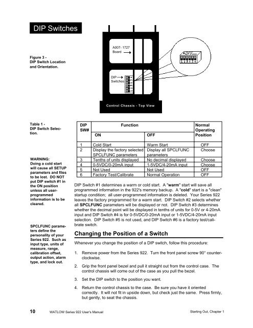
DIP SwitchesFigure 3 -DIP Switch Locationand Orientation.A007- 1727BoardDIPSwitchesControl Chassis - Top ViewTable 1 -DIP Switch Selection.WARNING:Doing a cold startwill cause all SETUPparameters and filesto be lost. DO NOTput DIP switch #1 inthe ON positionunless all userprogrammedinformation is to becleared.SPCLFUNC parametersdefine thepersonality of your<strong>Series</strong> <strong>922</strong>. Such asinput type, units ofmeasure, range,calibration offset,output action, alarmtype, and lock out.DIP Function NormalSW#OperatingON OFF Position1 Cold Start Warm Start OFF2 Display the factory selected Display all SPCLFUNC ChooseSPCLFUNC parameters parameters3 Tenths of units displayed No decimal displayed Choose4 0-5VDC/0-20mA input 1-5VDC/4-20mA input Choose5 Not Used Not Used OFF6 Factory Test/Calibrate Normal Operation OFFDIP Switch #1 determines a warm or cold start. A "warm" start will save allprogrammed information in the <strong>922</strong>'s memory backup. A "cold" start is a "clean"startup condition; all user-programmed information is deleted. Your <strong>Series</strong> <strong>922</strong>leaves the factory programmed for a warm start. DIP Switch #2 selects whetherall SPCLFUNC parameters will be displayed or not. DIP Switch #3 determineswhether the decimal point will be displayed in tenths of units for 0-5V or 4-20mAinput and DIP Switch #4 is for 0-5VDC/0-20mA input or 1-5VDC/4-20mA inputselection. DIP Switch #5 is not used, and DIP Switch #6 is a factory test/calibrateswitch.Changing the Position of a SwitchWhenever you change the position of a DIP switch, follow this procedure:1. Remove power from the <strong>Series</strong> <strong>922</strong>. Turn the front panel screw 90° counterclockwise.2. Grip the front panel bezel and pull it straight out from the control case. Thecontrol chassis will come out of the case as you pull the bezel.3. Set the DIP switch to the position you want.4. Return the control chassis to the case. Be sure you have it orientedcorrectly. It will not fit in upside down, but check just the same. Press firmly,but gently, to seat the chassis.10 WATLOW <strong>Series</strong> <strong>922</strong> <strong>User's</strong> <strong>Manual</strong> Starting Out, Chapter 1