Watlow Series 922 User's Manual - Heaters Sensors Controls
Watlow Series 922 User's Manual - Heaters Sensors Controls
Watlow Series 922 User's Manual - Heaters Sensors Controls
You also want an ePaper? Increase the reach of your titles
YUMPU automatically turns print PDFs into web optimized ePapers that Google loves.
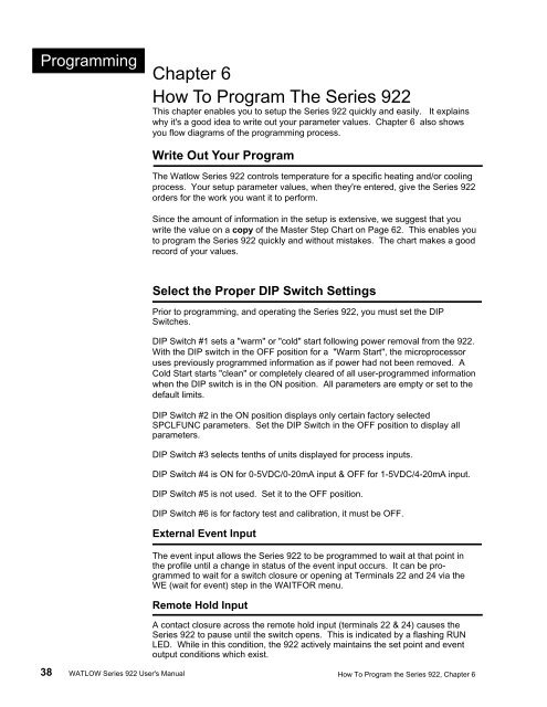
Programming Chapter 6How To Program The <strong>Series</strong> <strong>922</strong>This chapter enables you to setup the <strong>Series</strong> <strong>922</strong> quickly and easily. It explainswhy it's a good idea to write out your parameter values. Chapter 6 also showsyou flow diagrams of the programming process.Write Out Your ProgramThe <strong>Watlow</strong> <strong>Series</strong> <strong>922</strong> controls temperature for a specific heating and/or coolingprocess. Your setup parameter values, when they're entered, give the <strong>Series</strong> <strong>922</strong>orders for the work you want it to perform.Since the amount of information in the setup is extensive, we suggest that youwrite the value on a copy of the Master Step Chart on Page 62. This enables youto program the <strong>Series</strong> <strong>922</strong> quickly and without mistakes. The chart makes a goodrecord of your values.Select the Proper DIP Switch SettingsPrior to programming, and operating the <strong>Series</strong> <strong>922</strong>, you must set the DIPSwitches.DIP Switch #1 sets a "warm" or "cold" start following power removal from the <strong>922</strong>.With the DIP switch in the OFF position for a "Warm Start", the microprocessoruses previously programmed information as if power had not been removed. ACold Start starts "clean" or completely cleared of all user-programmed informationwhen the DIP switch is in the ON position. All parameters are empty or set to thedefault limits.DIP Switch #2 in the ON position displays only certain factory selectedSPCLFUNC parameters. Set the DIP Switch in the OFF position to display allparameters.DIP Switch #3 selects tenths of units displayed for process inputs.DIP Switch #4 is ON for 0-5VDC/0-20mA input & OFF for 1-5VDC/4-20mA input.DIP Switch #5 is not used. Set it to the OFF position.DIP Switch #6 is for factory test and calibration, it must be OFF.External Event InputThe event input allows the <strong>Series</strong> <strong>922</strong> to be programmed to wait at that point inthe profile until a change in status of the event input occurs. It can be programmedto wait for a switch closure or opening at Terminals 22 and 24 via theWE (wait for event) step in the WAITFOR menu.Remote Hold InputA contact closure across the remote hold input (terminals 22 & 24) causes the<strong>Series</strong> <strong>922</strong> to pause until the switch opens. This is indicated by a flashing RUNLED. While in this condition, the <strong>922</strong> actively maintains the set point and eventoutput conditions which exist.38 WATLOW <strong>Series</strong> <strong>922</strong> <strong>User's</strong> <strong>Manual</strong> How To Program the <strong>Series</strong> <strong>922</strong>, Chapter 6


