Watlow Series 922 User's Manual - Heaters Sensors Controls
Watlow Series 922 User's Manual - Heaters Sensors Controls
Watlow Series 922 User's Manual - Heaters Sensors Controls

You also want an ePaper? Increase the reach of your titles
YUMPU automatically turns print PDFs into web optimized ePapers that Google loves.
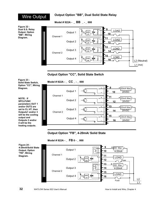
Wire OutputFigure 22 -Dual S.S. RelayOutput, Option"BB", WiringDiagram.Output Option "BB", Dual Solid State RelayModel # <strong>922</strong>A - _ BB _ - _ 0009LOADOutput 110Channel 111LOADOutput 21213LOADOutput 314Channel 215LOADOutput 416L2 (Neutral)L1 (Hot)Output Option "CC", Solid State SwitchFigure 23 -Solid State Switch,Option "CC", WiringDiagram.NOTE: IfSPCLFUNCparameters OUT 1and/or OUT2 areset to CL HT, thenOutputs1 and/or 3will be the coolingoutput andOutputs 2 and/or4 will be theheating outputs.Model # <strong>922</strong>A - _ CC _ - _ 000Output 1Channel 1Output 2Output 3Channel 2Output 491011121314151620mA Max20VDC20mA Max20VDC20mA Max20VDC20mA Max20VDCOutput Option "FB", 4-20mA/ Solid StateModel # <strong>922</strong>A - _ FB 0 - _ 000Figure 24 -4-20mA/Solid StateOutput, Option"FB", WiringDiagram.Channel 1Channel 2Output 1Output 2Output 3Output 4-910111213141516+600 Max-4-20mALOADFuse+ 600 Max4-20mALOADFuse-L2L132 WATLOW <strong>Series</strong> <strong>922</strong> <strong>User's</strong> <strong>Manual</strong> How to Install and Wire, Chapter 4