Watlow Series 922 User's Manual - Heaters Sensors Controls
Watlow Series 922 User's Manual - Heaters Sensors Controls
Watlow Series 922 User's Manual - Heaters Sensors Controls

You also want an ePaper? Increase the reach of your titles
YUMPU automatically turns print PDFs into web optimized ePapers that Google loves.
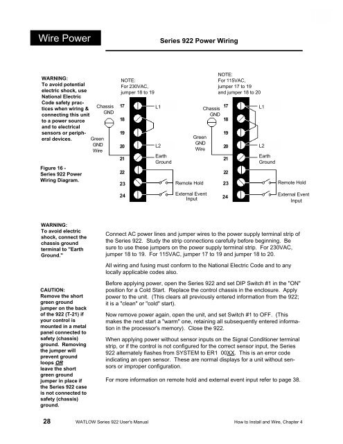
Wire Power<strong>Series</strong> <strong>922</strong> Power WiringWARNING:To avoid potentialelectric shock, useNational ElectricCode safety practiceswhen wiring &connecting this unitto a power sourceand to electricalsensors or peripheraldevices.Figure 16 -<strong>Series</strong> <strong>922</strong> PowerWiring Diagram.ChassisGNDGreenGNDWireNOTE:For 230VAC,jumper 18 to 1917181920212223L1 (Hot)L2 (Hot)EarthGroundGreenGNDWireRemote HoldChassisGNDNOTE:For 115VAC,jumper 17 to 19and jumper 18 to 2017181920212223L1 (Hot)L2 (Hot)EarthGroundRemote Hold24 External EventInput 24External EventInputWARNING:To avoid electricshock, connect thechassis groundterminal to "EarthGround."Connect AC power lines and jumper wires to the power supply terminal strip ofthe <strong>Series</strong> <strong>922</strong>. Study the strip connections carefully before beginning. Besure to use these jumpers on the power supply terminal strip. For 230VAC,jumper 18 to 19. For 115VAC, jumper 17 to 19 and jumper 18 to 20.All wiring and fusing must conform to the National Electric Code and to anylocally applicable codes also.CAUTION:Remove the shortgreen groundjumper on the backof the <strong>922</strong> (T-21) ifyour control ismounted in a metalpanel connected tosafety (chassis)ground. Removingthe jumper willprevent groundloops ORleave the shortgreen groundjumper in place ifthe <strong>Series</strong> <strong>922</strong> caseis not connected tosafety (chassis)ground.Before applying power, open the <strong>Series</strong> <strong>922</strong> and set DIP Switch #1 in the "ON"position for a Cold Start. Replace the control chassis in the enclosure. Applypower to the unit. (This clears all previously entered information from the <strong>922</strong>;it is a "clean" or "cold" start).Now remove power again, open the unit, and set Switch #1 to OFF. (Thismakes the next start a "warm" one, retaining all subsequently entered informationin the processor's memory). Close the <strong>922</strong>.When applying power without sensor inputs on the Signal Conditioner terminalstrip, or if the control is not configured for the correct sensor input, the <strong>Series</strong><strong>922</strong> alternately flashes from SYSTEM to ER1 00XX. This is an error codeindicating an open sensor. These are normal displays for a unit without sensorsor improper configuration.For more information on remote hold and external event input refer to page 38.28 WATLOW <strong>Series</strong> <strong>922</strong> <strong>User's</strong> <strong>Manual</strong> How to Install and Wire, Chapter 4