Watlow Series 922 User's Manual - Heaters Sensors Controls
Watlow Series 922 User's Manual - Heaters Sensors Controls
Watlow Series 922 User's Manual - Heaters Sensors Controls

Create successful ePaper yourself
Turn your PDF publications into a flip-book with our unique Google optimized e-Paper software.
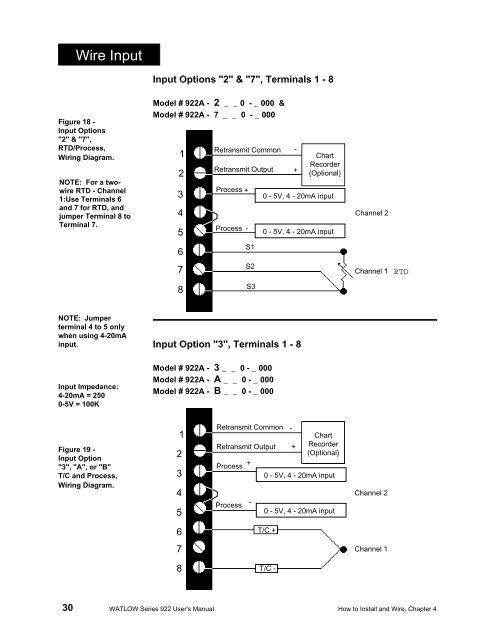
Wire InputInput Options "2" & "7", Terminals 1 - 8Figure 18 -Input Options"2" & "7",RTD/Process,Wiring Diagram.NOTE: For a twowireRTD - Channel1:Use Terminals 6and 7 for RTD, andjumper Terminal 8 toTerminal 7.Model # <strong>922</strong>A - 2 _ _ 0 - _ 000 &Model # <strong>922</strong>A - 7 _ _ 0 - _ 00012345Retransmit CommonRetransmit OutputProcess +Process --+ChartRecorder(Optional)0 - 5V, 4 - 20mA input0 - 5V, 4 - 20mA inputChannel 26S17S2Channel 1RTD8S3NOTE: Jumperterminal 4 to 5 onlywhen using 4-20mAinput.Input Impedance:4-20mA = 2500-5V = 100KInput Option "3", Terminals 1 - 8Model # <strong>922</strong>A - 3 _ _ 0 - _ 000Model # <strong>922</strong>A - A _ _ 0 - _ 000Model # <strong>922</strong>A - B _ _ 0 - _ 000Figure 19 -Input Option"3", "A", or "B"T/C and Process,Wiring Diagram.12345Retransmit CommonRetransmit OutputProcessProcess+--+ChartRecorder(Optional)0 - 5V, 4 - 20mA input0 - 5V, 4 - 20mA inputChannel 26T/C +7Channel 18T/C -30 WATLOW <strong>Series</strong> <strong>922</strong> <strong>User's</strong> <strong>Manual</strong> How to Install and Wire, Chapter 4