- Page 2:
Engineering Geology
- Page 6:
Engineering Geology Second Edition
- Page 10:
Preface As noted in the Preface to
- Page 14:
Contents 1. Rock Types and Stratigr
- Page 18:
Contents Field Instrumentation 344
- Page 22:
Chapter 1 Rock Types and Stratigrap
- Page 26:
Chapter 1 several tens of metres bu
- Page 30:
Chapter 1 Figure 1.4 Distribution o
- Page 34:
Chapter 1 Figure 1.5 Lapilli near C
- Page 38:
Chapter 1 Figure 1.7 (a) Ropy or pa
- Page 42:
Chapter 1 Figure 1.8 Columnar joint
- Page 46:
Chapter 1 Figure 1.9 Pegmatite vein
- Page 50:
Chapter 1 Figure 1.10 Thin section
- Page 54:
Chapter 1 Figure 1.11 An old quarry
- Page 58:
Chapter 1 a b Figure 1.13 (a) Gneis
- Page 62:
Chapter 1 and the types of country
- Page 66:
Chapter 1 A variety of minerals suc
- Page 70:
Chapter 1 metasomatic activity is c
- Page 74:
Chapter 1 derived by partial intras
- Page 78:
Chapter 1 character (are they irreg
- Page 82:
Chapter 1 the top. Individual grade
- Page 86:
Chapter 1 Figure 1.20 Thin section
- Page 90:
Chapter 1 Montmorillonite [(Mg,Al)
- Page 94:
Chapter 1 Figure 1.22 Salt teepees
- Page 98:
Chapter 1 The extent and regularity
- Page 102:
Chapter 1 the lowest bed in the upp
- Page 106:
Table 1.1. The geological timescale
- Page 110:
Chapter 1 The principal way in whic
- Page 114:
Chapter 2 Geological Structures The
- Page 118:
Chapter 2 (b) Figure 2.2 (a) Block
- Page 122:
Chapter 2 (b) Figure 2.4 (a) Types
- Page 126:
Chapter 2 Figure 2.6 Chevron fold i
- Page 130:
Chapter 2 direction of extension. T
- Page 134:
Chapter 2 Figure 2.9 Types of fault
- Page 138:
Chapter 2 Figure 2.11 (a) Repetitio
- Page 142:
Chapter 2 side of a fault are of di
- Page 146:
Chapter 2 Figure 2.14 Geometric ori
- Page 150:
Chapter 2 As joints represent surfa
- Page 154:
Chapter 2 (several metres). The int
- Page 158:
Chapter 2 Strength of Discontinuous
- Page 162:
Chapter 2 Table 2.5. Classification
- Page 166:
73 Figure 2.17 Discontinuity survey
- Page 170:
Chapter 2 Figure 2.19 Representatio
- Page 174:
Chapter 3 Surface Processes All lan
- Page 178:
Chapter 3 humid regions more than d
- Page 182:
Chapter 3 Figure 3.3 Honeycomb weat
- Page 186:
Chapter 3 less soluble than limesto
- Page 190:
Chapter 3 Figure 3.4 The slake-dura
- Page 194:
Chapter 3 Because weathering brings
- Page 198:
Chapter 3 Figure 3.6 Approaches to
- Page 202:
Chapter 3 Figure 3.7 Valley bulging
- Page 206:
Chapter 3 Internal slides are usual
- Page 210:
Chapter 3 Figure 3.8 A classificati
- Page 214:
Chapter 3 Figure 3.10 Block diagram
- Page 218:
Chapter 3 direct factor in causing
- Page 222:
Chapter 3 Figure 3.14 (a) Trellised
- Page 226:
Chapter 3 Throughout its length, a
- Page 230:
Chapter 3 Figure 3.17 (a) Paired ri
- Page 234:
Chapter 3 Figure 3.18 Component par
- Page 238:
Chapter 3 In the early stages of ri
- Page 242:
Chapter 3 Karst Topography and Unde
- Page 246:
Chapter 3 Figure 3.22 Appearance of
- Page 250:
Chapter 3 the surface throughout th
- Page 254:
Chapter 3 Figure 3.25 Drumlins, nea
- Page 258:
Chapter 3 barrier, the threshold, o
- Page 262:
Chapter 3 Most melt water streams t
- Page 266:
Chapter 3 Other small ridge-like ka
- Page 270:
Chapter 3 of perennially frozen gro
- Page 274:
Chapter 3 Wind Action Wind erosion
- Page 278:
Chapter 3 Figure 3.32 Buttes and me
- Page 282:
Chapter 3 areas in which there is e
- Page 286:
Chapter 3 commonly falls in both in
- Page 290:
Chapter 3 Figure 3.35 Terminology o
- Page 294:
Chapter 3 disrupts their pattern of
- Page 298:
Chapter 3 is extended out to sea. B
- Page 302:
Chapter 3 (a) (b) Figure 3.37 (Cont
- Page 306:
Chapter 3 Table 3.2. Average beach
- Page 310:
Figure 3.38 Hurst Castle Spit with
- Page 314:
Chapter 3 windspeeds of approximate
- Page 318:
Chapter 3 Free oscillations develop
- Page 322:
Chapter 4 Groundwater Conditions an
- Page 326:
Chapter 4 Figure 4.1 Map of part of
- Page 330:
Chapter 4 buried upper surface of a
- Page 334:
Chapter 4 Table 4.2. Soil suction p
- Page 338:
Chapter 4 The factors affecting the
- Page 342:
Chapter 4 Table 4.3. Some examples
- Page 346:
Chapter 4 Permeability and porosity
- Page 350:
Chapter 4 Flow through Soils and Ro
- Page 354:
Chapter 4 General Equation of Flow
- Page 358:
Chapter 4 and k h H / k + H / k + H
- Page 362:
Chapter 4 Figure 4.8 Standard piezo
- Page 366:
Chapter 4 velocity of the upward se
- Page 370:
Geological mapping frequently forms
- Page 374:
Chapter 4 As groundwater moves from
- Page 378:
Chapter 4 Figure 4.9 Drillhole pack
- Page 382:
Chapter 4 Figure 4.10 Yield drawdow
- Page 386:
Chapter 4 Figure 4.11 Flow net bene
- Page 390:
Chapter 4 in sedimentary rocks. The
- Page 394:
Chapter 4 Figure 4.12 Gravel-packed
- Page 398:
Chapter 4 In addition, the fracture
- Page 402:
Chapter 4 to another as groundwater
- Page 406:
Chapter 4 Figure 4.14 An example of
- Page 410:
Chapter 4 Many of the VOCs are liqu
- Page 414:
Chapter 4 Table 4.7. Composition of
- Page 418:
Chapter 4 Migration control is cons
- Page 422:
Description, Properties and Behavio
- Page 426:
Chapter 5 Table 5.2.—Cont’d. In
- Page 430:
Chapter 5 Table 5.2.—Cont’d. In
- Page 434:
Chapter 5 Table 5.3b. Plasticity ac
- Page 438:
Chapter 5 Table 5.6. Mixed coarse s
- Page 442:
Chapter 5 reduced accordingly, henc
- Page 446:
Chapter 5 enough cement to develop
- Page 450:
Chapter 5 Figure 5.2 Particle size
- Page 454:
Chapter 5 this was indicative of me
- Page 458:
Chapter 5 Table 5.12. Particle size
- Page 462:
Chapter 5 Table 5.13. USAEWES class
- Page 466:
Chapter 5 Table 5.14. Range of comp
- Page 470:
Chapter 5 sensitivity, namely, inse
- Page 474:
Chapter 5 Table 5.15. Strength of w
- Page 478:
Chapter 5 They differ from laterite
- Page 482:
Chapter 5 (a) (b) Figure 5.7 (a) Po
- Page 486:
Chapter 5 supply of sand, the wind
- Page 490:
Chapter 5 Tills and Other Glacially
- Page 494:
Chapter 5 Figure 5.11 Variation in
- Page 498:
Chapter 5 Table 5.18a. A weathering
- Page 502:
Chapter 5 Table 5.19. Some properti
- Page 506:
Chapter 5 thick, or as ice wedges.
- Page 510:
Chapter 5 Figure 5.14 Increase in c
- Page 514:
Chapter 5 Organic Soils: Peat Peat
- Page 518:
Chapter 5 when peat possesses high
- Page 522:
Chapter 5 and the discontinuities t
- Page 526:
Genetic/group Metamorphic Igneous U
- Page 530:
Chapter 5 Table 5.25. Grades of unc
- Page 534:
Chapter 5 which lavas, pyroclasts a
- Page 538:
Chapter 5 preferred orientation. Ge
- Page 542:
Chapter 5 Table 5.30. Some geomecha
- Page 546:
Table 5.31. Some geomechanical prop
- Page 550:
Chapter 5 When a load is applied to
- Page 554:
Chapter 5 Furthermore, carbonate ro
- Page 558:
Chapter 5 water that drains into li
- Page 562:
Table 5.33. Some physical propertie
- Page 566:
Chapter 5 Evaporites The dry densit
- Page 570:
Chapter 5 suggest that the rock is
- Page 574:
Chapter 6 Geological Materials Used
- Page 578:
Chapter 6 one of the shortcomings o
- Page 582:
Stancliffe Buff Fine to Namurian me
- Page 586:
Chapter 6 drainage and escape of mo
- Page 590:
Chapter 6 Figure 6.2 Black crust de
- Page 594:
Chapter 6 Limestones show a variati
- Page 598:
Chapter 6 Figure 6.4 Coarse-grained
- Page 602:
Chapter 6 Usually, armourstone is s
- Page 606:
Chapter 6 The crushing strength of
- Page 610:
Chapter 6 the polishing action of t
- Page 614:
Chapter 6 a poor ability to absorb
- Page 618:
Chapter 6 crushing plant. After cru
- Page 622:
Chapter 6 Alluvial cones are found
- Page 626:
Chapter 6 Ball clays and china clay
- Page 630:
Chapter 6 Sulphate minerals in mudr
- Page 634:
Chapter 6 is to be extracted (Bell,
- Page 638:
Chapter 6 clay, or they may be brou
- Page 642:
Chapter 7 Site Investigation The ge
- Page 646:
Chapter 7 factors throughout this s
- Page 650:
Chapter 7 Infrared linescanning is
- Page 654:
Chapter 7 by satellites 800 km out
- Page 658:
Chapter 7 Table 7.2. Types of photo
- Page 662:
Chapter 7 Figure 7.1 Drillhole log.
- Page 666:
Chapter 7 Figure 7.2 Light cable an
- Page 670:
Chapter 7 Figure 7.3 Wash-boring ri
- Page 674:
Chapter 7 Figure 7.4 The general-pu
- Page 678:
Chapter 7 Figure 7.6 Section throug
- Page 682:
Chapter 7 Figure 7.8 Rotary percuss
- Page 686:
Chapter 7 Figure 7.11 Double-tube s
- Page 690:
Chapter 7 Figure 7.12 Standard pene
- Page 694:
Chapter 7 Figure 7.13 An electric p
- Page 698:
Chapter 7 Figure 7.15 Shear vane te
- Page 702:
Chapter 7 provide a sufficiently st
- Page 706:
Chapter 7 Figure 7.18 (a) Schematic
- Page 710:
Chapter 7 movements are needed in c
- Page 714:
Chapter 7 Figure 7.22 Borehole incl
- Page 718:
Chapter 7 hemispherical wave front
- Page 722:
Chapter 7 The most common arrangeme
- Page 726:
Chapter 7 Table 7.5. Resistivity of
- Page 730:
Chapter 7 Figure 7.25 Wenner and Sc
- Page 734:
Chapter 7 As a consequence, the met
- Page 738:
Chapter 7 Figure 7.26 Magnetometer
- Page 742:
Chapter 7 north-south distance, the
- Page 746:
Chapter 7 large SPs, whereas shales
- Page 750:
Chapter 7 the foundation conditions
- Page 754:
Chapter 7 Figure 7.29 Geomorphologi
- Page 758:
Chapter 7 purpose, have a larger sc
- Page 762:
Table 7.7a. Excerpts from the engin
- Page 766:
6b Chiefly Widespread in 10-13, 18-
- Page 770:
Table 7.8. Advantages and disadvant
- Page 774:
Chapter 8 Geology, Planning and Dev
- Page 778:
Chapter 8 It therefore is important
- Page 782:
Chapter 8 If there are no mitigatio
- Page 786:
Chapter 8 Figure 8.2 (a) An example
- Page 790:
Chapter 8 to nueés ardentes, the e
- Page 794:
387 Figure 8.3 (a) Preliminary haza
- Page 798:
Chapter 8 An earthquake propagates
- Page 802:
IX Ruinous. General panic. Masonry
- Page 806:
Chapter 8 standing in earthquakes t
- Page 810:
Chapter 8 In earthquake prone areas
- Page 814:
Chapter 8 Figure 8.7 Microseismic z
- Page 818:
Chapter 8 Figure 8.8 Landslide susc
- Page 822:
Chapter 8 concentrated into channel
- Page 826:
Chapter 8 magnitude or greater occu
- Page 830:
Chapter 8 occurs on average once in
- Page 834:
Chapter 8 Figure 8.12 Revetment com
- Page 838:
Chapter 8 Dunes act as barriers, en
- Page 842:
Chapter 8 Artificial replenishment
- Page 846:
Chapter 8 Figure 8.16 A breakwater
- Page 850:
Chapter 8 record of tsunamis is req
- Page 854:
Chapter 8 Movement of sand can bury
- Page 858:
Table 8.3. Objectives and methods o
- Page 862:
Chapter 8 Soil erosion by water is
- Page 866:
Chapter 8 The redistribution and re
- Page 870:
Chapter 8 Figure 8.19 Cellular cons
- Page 874:
Chapter 8 recommended that at dry s
- Page 878:
Chapter 8 Disposal of liquid hazard
- Page 882:
Chapter 8 any heat produced by radi
- Page 886:
Chapter 8 Tailings may also contain
- Page 890:
Chapter 8 The mining method is a ve
- Page 894:
Chapter 8 Figure 8.25 An example of
- Page 898:
Chapter 8 has passed by, the ground
- Page 902:
Chapter 8 Figure 8.27 Earth fissure
- Page 906:
Chapter 8 Figure 8.28 A tension sca
- Page 910:
Chapter 8 sinkholes and produced di
- Page 914:
Chapter 8 Figure 8.30 A survey of d
- Page 918:
Chapter 8 Figure 8.31 The Big Hole,
- Page 922:
Chapter 8 with various previous use
- Page 926:
Chapter 9 Geology and Construction
- Page 930:
Chapter 9 and there is no alternati
- Page 934:
Chapter 9 The ease of drilling in r
- Page 938:
Figure 9.1 Charge Q as a function o
- Page 942:
Table 9.1. Rippability rating chart
- Page 946: Chapter 9 Table 9.2. Density, bulki
- Page 950: Chapter 9 Figure 9.6 Dentition and
- Page 954: Chapter 9 Figure 9.8 Reinforced ear
- Page 958: Chapter 9 (a) (b) Figure 9.10 (a) S
- Page 962: Chapter 9 of probe holes that fan o
- Page 966: Chapter 9 Weathering of rocks leads
- Page 970: Chapter 9 of the ground. If the str
- Page 974: Chapter 9 and the dissipation of re
- Page 978: methane toxic, it also is combustib
- Page 982: Chapter 9 Bentonite slurry is used
- Page 986: Chapter 9 some cutters are broken b
- Page 990: Chapter 9 but occasionally it is us
- Page 994: Table 9.4. The rock mass rating sys
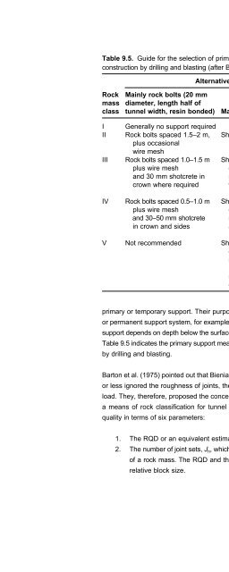
- Page 1000: 490 Table 9.6. Classification of in
- Page 1004: 492 Table 9.6. Classification of in
- Page 1008: 494 Table 9.6. Classification of in
- Page 1012: E n g i n e e r i n g G e o l o g y
- Page 1016: E n g i n e e r i n g G e o l o g y
- Page 1020: E n g i n e e r i n g G e o l o g y
- Page 1024: E n g i n e e r i n g G e o l o g y
- Page 1028: E n g i n e e r i n g G e o l o g y
- Page 1032: E n g i n e e r i n g G e o l o g y
- Page 1036: E n g i n e e r i n g G e o l o g y
- Page 1040: E n g i n e e r i n g G e o l o g y
- Page 1044: E n g i n e e r i n g G e o l o g y
- Page 1048:
E n g i n e e r i n g G e o l o g y
- Page 1052:
E n g i n e e r i n g G e o l o g y
- Page 1056:
E n g i n e e r i n g G e o l o g y
- Page 1060:
E n g i n e e r i n g G e o l o g y
- Page 1064:
E n g i n e e r i n g G e o l o g y
- Page 1068:
E n g i n e e r i n g G e o l o g y
- Page 1072:
E n g i n e e r i n g G e o l o g y
- Page 1076:
E n g i n e e r i n g G e o l o g y
- Page 1080:
E n g i n e e r i n g G e o l o g y
- Page 1084:
532 Table 9.8. Typical compaction c
- Page 1088:
E n g i n e e r i n g G e o l o g y
- Page 1092:
E n g i n e e r i n g G e o l o g y
- Page 1096:
E n g i n e e r i n g G e o l o g y
- Page 1100:
E n g i n e e r i n g G e o l o g y
- Page 1104:
E n g i n e e r i n g G e o l o g y
- Page 1108:
E n g i n e e r i n g G e o l o g y
- Page 1112:
E n g i n e e r i n g G e o l o g y
- Page 1116:
E n g i n e e r i n g G e o l o g y
- Page 1120:
E n g i n e e r i n g G e o l o g y
- Page 1124:
E n g i n e e r i n g G e o l o g y
- Page 1128:
E n g i n e e r i n g G e o l o g y
- Page 1132:
E n g i n e e r i n g G e o l o g y
- Page 1136:
This page intentionally left blank
- Page 1140:
E n g i n e e r i n g G e o l o g y
- Page 1144:
E n g i n e e r i n g G e o l o g y
- Page 1148:
E n g i n e e r i n g G e o l o g y
- Page 1152:
E n g i n e e r i n g G e o l o g y
- Page 1156:
E n g i n e e r i n g G e o l o g y
- Page 1160:
E n g i n e e r i n g G e o l o g y
- Page 1164:
E n g i n e e r i n g G e o l o g y
- Page 1168:
E n g i n e e r i n g G e o l o g y
- Page 1172:
I n d e x coastal protection, 410,
- Page 1176:
I n d e x grout, 526, 548 groutabil
- Page 1180:
I n d e x rebound, 513 recumbent fo
- Page 1184:
This page intentionally left blank