

Hacking_and_Penetration_Testing_with_Low_Power_Devices

You also want an ePaper? Increase the reach of your titles
YUMPU automatically turns print PDFs into web optimized ePapers that Google loves.
BeagleBone capes<br />
131<br />
pull-up resistor. Pins A0 <strong>and</strong> A1 should also be tied high, but two jumpers or dip<br />
switches must be used to allow these pins to be tied low. This 2-bit addressing of<br />
capes allows up to four capes to be installed assuming that the signals used by each<br />
cape allow interoperation.<br />
After a BeagleBone has booted, a cape manager process will read the EEPROMs<br />
of all connected capes. The format for the EEPROM data can be found in the System<br />
Reference Manual. Data stored include board name, manufacturer, version, number<br />
of pins used, maximum currents on each bus, <strong>and</strong> pin configuration information.<br />
There are 74 configurable pins out of the 92 pins on the BeagleBone expansion<br />
headers. Two bytes is required to describe the configuration of each pin. The cape<br />
manager uses this information to ensure proper cape configuration. A prototype<br />
board or other cape that lacks an EEPROM will require that appropriate device tree<br />
overlays be manually loaded. Device tree overlays will be described briefly later in<br />
this chapter.<br />
XBee MINI-CAPE<br />
As previously discussed, we will use IEEE 802.15.4 or XBee networking to remotely<br />
comm<strong>and</strong> our army of hacking drones. If you want more than just a few drones, using<br />
a cape to connect your XBee modems might be preferable to hardwiring the modems<br />
as described early in this chapter. We’ll get our feet wet <strong>with</strong> an XBee min-cape.<br />
The mini-cape presented here is easily built <strong>with</strong> hobby printed circuit board<br />
(PCB) kits. The single-sided (copper trace on one side only) board is a mere 1.25<br />
2.20 in.. Several of these can be made from commonly available board sizes. There<br />
are a number of ways to produce small circuit boards. Do not fear if you have never<br />
done something like this before.<br />
The mini-cape <strong>and</strong> other boards presented in this book were created using the<br />
popular EAGLE CAD software from CadSoft (http://www.cadsoftusa.com/eaglepcb-design-software).<br />
CadSoft offers a lot of EAGLE licensing levels. There is a free<br />
version of EAGLE limited to smaller boards <strong>with</strong> two or less signal layers that are<br />
more than sufficient for creating BeagleBone capes.<br />
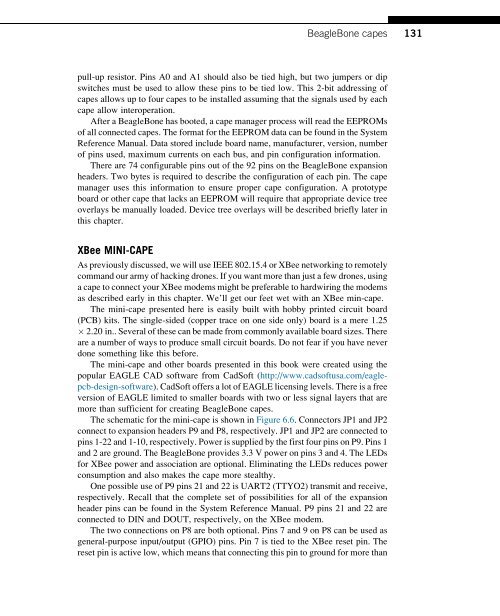
The schematic for the mini-cape is shown in Figure 6.6. Connectors JP1 <strong>and</strong> JP2<br />
connect to expansion headers P9 <strong>and</strong> P8, respectively. JP1 <strong>and</strong> JP2 are connected to<br />
pins 1-22 <strong>and</strong> 1-10, respectively. <strong>Power</strong> is supplied by the first four pins on P9. Pins 1<br />
<strong>and</strong> 2 are ground. The BeagleBone provides 3.3 V power on pins 3 <strong>and</strong> 4. The LEDs<br />
for XBee power <strong>and</strong> association are optional. Eliminating the LEDs reduces power<br />
consumption <strong>and</strong> also makes the cape more stealthy.<br />
One possible use of P9 pins 21 <strong>and</strong> 22 is UART2 (TTYO2) transmit <strong>and</strong> receive,<br />
respectively. Recall that the complete set of possibilities for all of the expansion<br />
header pins can be found in the System Reference Manual. P9 pins 21 <strong>and</strong> 22 are<br />
connected to DIN <strong>and</strong> DOUT, respectively, on the XBee modem.<br />
The two connections on P8 are both optional. Pins 7 <strong>and</strong> 9 on P8 can be used as<br />
general-purpose input/output (GPIO) pins. Pin 7 is tied to the XBee reset pin. The<br />
reset pin is active low, which means that connecting this pin to ground for more than