VersaLASER® (VLS) User Guide VLS2.30, VLS3.50
VersaLASER® (VLS) User Guide VLS2.30, VLS3.50
VersaLASER® (VLS) User Guide VLS2.30, VLS3.50

You also want an ePaper? Increase the reach of your titles
YUMPU automatically turns print PDFs into web optimized ePapers that Google loves.
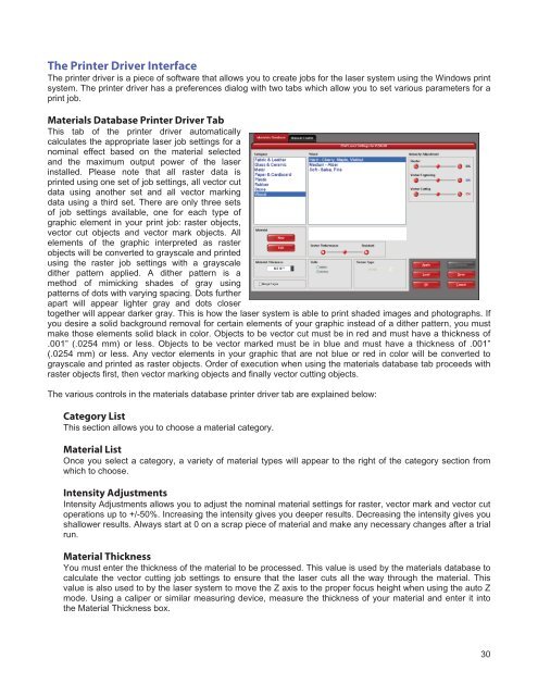
The Printer Driver Interface<br />
The printer driver is a piece of software that allows you to create jobs for the laser system using the Windows print<br />
system. The printer driver has a preferences dialog with two tabs which allow you to set various parameters for a<br />
print job.<br />
Materials Database Printer Driver Tab<br />
This tab of the printer driver automatically<br />
calculates the appropriate laser job settings for a<br />
nominal effect based on the material selected<br />
and the maximum output power of the laser<br />
installed. Please note that all raster data is<br />
printed using one set of job settings, all vector cut<br />
data using another set and all vector marking<br />
data using a third set. There are only three sets<br />
of job settings available, one for each type of<br />
graphic element in your print job: raster objects,<br />
vector cut objects and vector mark objects. All<br />
elements of the graphic interpreted as raster<br />
objects will be converted to grayscale and printed<br />
using the raster job settings with a grayscale<br />
dither pattern applied. A dither pattern is a<br />
method of mimicking shades of gray using<br />
patterns of dots with varying spacing. Dots further<br />
apart will appear lighter gray and dots closer<br />
together will appear darker gray. This is how the laser system is able to print shaded images and photographs. If<br />
you desire a solid background removal for certain elements of your graphic instead of a dither pattern, you must<br />
make those elements solid black in color. Objects to be vector cut must be in red and must have a thickness of<br />
.001” (.0254 mm) or less. Objects to be vector marked must be in blue and must have a thickness of .001”<br />
(.0254 mm) or less. Any vector elements in your graphic that are not blue or red in color will be converted to<br />
grayscale and printed as raster objects. Order of execution when using the materials database tab proceeds with<br />
raster objects first, then vector marking objects and finally vector cutting objects.<br />
The various controls in the materials database printer driver tab are explained below:<br />
Category List<br />
This section allows you to choose a material category.<br />
Material List<br />
Once you select a category, a variety of material types will appear to the right of the category section from<br />
which to choose.<br />
Intensity Adjustments<br />
Intensity Adjustments allows you to adjust the nominal material settings for raster, vector mark and vector cut<br />
operations up to +/-50%. Increasing the intensity gives you deeper results. Decreasing the intensity gives you<br />
shallower results. Always start at 0 on a scrap piece of material and make any necessary changes after a trial<br />
run.<br />
Material Thickness<br />
You must enter the thickness of the material to be processed. This value is used by the materials database to<br />
calculate the vector cutting job settings to ensure that the laser cuts all the way through the material. This<br />
value is also used to by the laser system to move the Z axis to the proper focus height when using the auto Z<br />
mode. Using a caliper or similar measuring device, measure the thickness of your material and enter it into<br />
the Material Thickness box.<br />
30