VersaLASER® (VLS) User Guide VLS2.30, VLS3.50
VersaLASER® (VLS) User Guide VLS2.30, VLS3.50
VersaLASER® (VLS) User Guide VLS2.30, VLS3.50

Create successful ePaper yourself
Turn your PDF publications into a flip-book with our unique Google optimized e-Paper software.
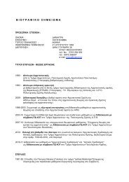
5. Locate the self-aligning electrical connector (1) and two alignment holes (2) on the underside of the<br />
cutting table.<br />
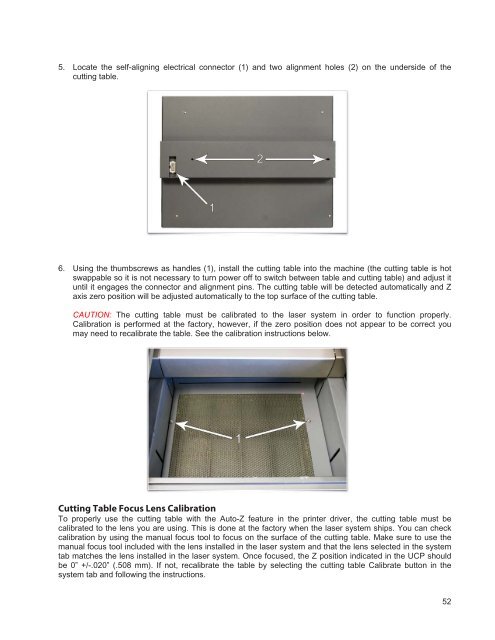
6. Using the thumbscrews as handles (1), install the cutting table into the machine (the cutting table is hot<br />
swappable so it is not necessary to turn power off to switch between table and cutting table) and adjust it<br />
until it engages the connector and alignment pins. The cutting table will be detected automatically and Z<br />
axis zero position will be adjusted automatically to the top surface of the cutting table.<br />
CAUTION: The cutting table must be calibrated to the laser system in order to function properly.<br />
Calibration is performed at the factory, however, if the zero position does not appear to be correct you<br />
may need to recalibrate the table. See the calibration instructions below.<br />
Cutting Table Focus Lens Calibration<br />
To properly use the cutting table with the Auto-Z feature in the printer driver, the cutting table must be<br />
calibrated to the lens you are using. This is done at the factory when the laser system ships. You can check<br />
calibration by using the manual focus tool to focus on the surface of the cutting table. Make sure to use the<br />
manual focus tool included with the lens installed in the laser system and that the lens selected in the system<br />
tab matches the lens installed in the laser system. Once focused, the Z position indicated in the UCP should<br />
be 0” +/-.020” (.508 mm). If not, recalibrate the table by selecting the cutting table Calibrate button in the<br />
system tab and following the instructions.<br />
52