Super Multi System - Toshiba
Super Multi System - Toshiba
Super Multi System - Toshiba

Create successful ePaper yourself
Turn your PDF publications into a flip-book with our unique Google optimized e-Paper software.
26<br />
Diagnostic procedure<br />
Outdoor unit<br />
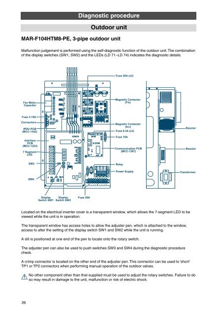
MAR-F104HTM8-PE, 3-pipe outdoor unit<br />
Malfunction judgement is performed using the self-diagnostic function of the outdoor unit. The combination<br />
of the display switches (SW1, SW2) and the LEDs (LD 71~LD 74) indicates the diagnostic details.<br />
Located on the electrical inverter cover is a transparent window, which allows the 7-segment LED to be<br />
viewed while the unit is in operation.<br />
The transparent window has access holes to allow the adjuster pen, which is attached to the window,<br />
access to alter the setting of the display switch SW1 and SW2 while the unit is running.<br />
A slit is positioned at one end of the pen to locate onto the rotary switch.<br />
The adjuster pen can also be used to push switches SW3 and SW4 during the diagnostic procedure<br />
check.<br />
A crimp connector is located on the other end of the adjuster pen. This connector can be used to ‘short’<br />
TP1 or TP2 connectors when performing manual operation of the outdoor valves.<br />
No other component other than that supplied must be used to adjust the rotary switches. Failure to do<br />
so may result in damage to the unit, malfunction or risk of electric shock.