Super Multi System - Toshiba
Super Multi System - Toshiba
Super Multi System - Toshiba

Create successful ePaper yourself
Turn your PDF publications into a flip-book with our unique Google optimized e-Paper software.
Refrigerant pipe installation<br />
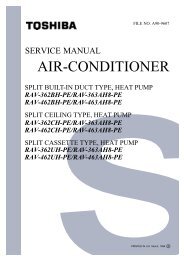
Additional refrigerant charging method<br />
(1) Loosely connect the refrigerant cylinder hose to the gauge manifold, then open the source valve V H on<br />
the cylinder, purge the air in the hose, and then tighten the hose.<br />
(2) As shown in the diagram below, turn the refrigerant cylinder upside down, open the valve V H on the<br />
gauge manifold, and then charge the liquid side pipe with refrigerant in the liquid state. (Note that with<br />
some types of refrigerant cylinders, the liquid refrigerant will be output through siphoning action with<br />
the cylinder in the normal upright position.) If the proper charging amount cannot be reached, close<br />
the valve V H , turn the refrigerant cylinder upright, open the liquid-side and balance packed valves<br />
completely, and open the gas-side packed valve only half way. Begin the cooling operation, open<br />
valve V L , and then charge the gas-side pipe with refrigerant in the liquid state.<br />
(3) While watching the scales display, quickly close the valve V L completely when the system has been<br />
charged with the proper amount of additional refrigerant. Then close the source valve V a on the<br />
cylinder, and open the gas-side packed valve completely.<br />
(4) Record the amount of additional refrigerant that was added to the system on the nameplate inside the<br />
front panel (lower) of the outdoor unit.<br />
Liquid pipe<br />
Gauge manifold<br />
4.5 5.5 7.0<br />
Indoor unit<br />
Gas pipe<br />
Refrigerant<br />
bottle<br />
V a<br />
Scales<br />
Gas<br />
Liquid<br />
Low High<br />
pressure pressure<br />
V L<br />
V H<br />
Packed valve<br />
(liquid side)<br />
Packed valve (discharge gas side)<br />
Refrigerant Outdoor unit<br />
gas<br />
73