

The Geometry of Ships

You also want an ePaper? Increase the reach of your titles
YUMPU automatically turns print PDFs into web optimized ePapers that Google loves.
THE GEOMETRY OF SHIPS 25<br />
A typical computational method might take the following<br />
steps:<br />
• Intersect two meshes to find candidate starting<br />
locations.<br />
• Use Newton-Raphson iteration to refine such a start,<br />
finding one accurate point on a candidate intersection.<br />
• “Tracking”: Use further Newton-Raphson steps to find<br />
a series <strong>of</strong> intersection points stepping along the intersection.<br />
Be prepared to take smaller steps if the curvature<br />
<strong>of</strong> the intersection increases.<br />
• Terminate tracking when you come to an edge <strong>of</strong> either<br />
surface, or return to the starting point <strong>of</strong> a closed loop.<br />
• Assemble the two directions into a single curve and<br />
select a suitable parameterization for it.<br />
• Substitute a spline approximation for the intersection<br />
as a 3-D curve, and two other spline approximations as<br />
2-D parametric curves in each <strong>of</strong> the surfaces.<br />
However, you can see that this simplified procedure<br />
does not deal with the majority <strong>of</strong> the difficulties mentioned<br />
in the preceding paragraph.<br />
An obvious conclusion from this list <strong>of</strong> difficulties is<br />
to avoid surface-surface intersections as much as possible.<br />
Nevertheless, most CAD systems are heavily dependent<br />
on such intersections. Users are encouraged to<br />
generate oversize surfaces that deliberately intersect,<br />
solve for intersections, and trim <strong>of</strong>f the excess. This one<br />
problem explains the bulk <strong>of</strong> the slow performance and<br />
unstable behavior that is so common in solid modeling<br />
s<strong>of</strong>tware.<br />
Relational geometry provides construction methods<br />
for durable “watertight” junctions that can frequently<br />
avoid surface-surface intersection. <strong>The</strong>se <strong>of</strong>ten take the<br />
form <strong>of</strong> designing the intersection as an explicit curve,<br />
then building the surfaces to meet it. Two transfinite surfaces<br />
that share a common edge curve will join accurately<br />
and durably along that edge. A transfinite surface<br />
that meets a snake on another surface will make a<br />
durable, watertight join. An intersection <strong>of</strong> a surface<br />
with a plane, circular cylinder, or sphere can be cut<br />
much more efficiently by an implicit surface. Intersections<br />
with general cylinders and cones are performed<br />
much more efficiently as projections.<br />
Nevertheless, there are situations where surface-surface<br />
intersections are unavoidable, so there is an<br />
Intersection snake (IntSnake) that encapsulates this<br />
process. <strong>The</strong> IntSnake is supported by a magnet on the<br />
host surface, which is used as a starting location for the<br />
initial search; this helps select the desired intersection<br />
curve when there are two or more intersections, and<br />
also specifies the desired parametric orientation.<br />
4.16 Trimmed Surfaces. A general limitation <strong>of</strong> parametric<br />
surfaces is that they are basically four-sided<br />
objects. This characteristic arises fundamentally from<br />
the rectangular domain in the u, v parameter space. If<br />
we look around us at the world <strong>of</strong> manufactured goods,<br />
we see a lot <strong>of</strong> surfaces that are four-sided, but there<br />
are a lot <strong>of</strong> other surfaces that are not. Parametric surfaces<br />
with three sides are generally supported in CAD<br />
by allowing one edge <strong>of</strong> a four-sided patch to be degenerate,<br />
but this requires a coordinate singularity (pole)<br />
at one <strong>of</strong> the three corners (Fig. 11). Parametric surfaces<br />
with more than four sides are also possible (e.g.,<br />
a Coons patch with a knuckle in one or more <strong>of</strong> its<br />
sides), but such a surface will have awkward slope discontinuities<br />
in its interior. A parametric surface with a<br />
smooth (e.g., circular or oval) outline, with no corners,<br />
is also possible, but involves either a pole singularity<br />
somewhere in the interior, two poles on the boundary,<br />
or “squash” singularities at two or four places on the<br />
boundary. Surface slopes and curvatures are likely to<br />
be irregular at any <strong>of</strong> these coordinate singularities or<br />
discontinuities.<br />
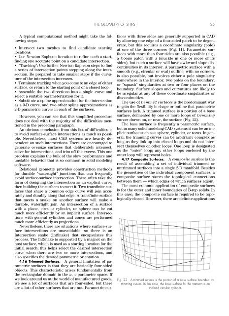
<strong>The</strong> use <strong>of</strong> trimmed surfaces is the predominant way<br />
to gain the flexibility in shape or outline that parametric<br />
surfaces lack. A trimmed surface is a portion <strong>of</strong> a base<br />
surface, delineated by one or more loops <strong>of</strong> trimming<br />
curves drawn on, or near, the surface (Fig. 22).<br />
<strong>The</strong> base surface is frequently a parametric surface,<br />
but in many solid modeling CAD systems it can be an implicit<br />
surface such as a sphere, cylinder, or torus. In general,<br />
the trimming curves can be arbitrarily complex as<br />
long as they link up into closed loops and do not intersect<br />
themselves or other loops. One loop is designated<br />
as the “outer” loop; any other loops enclosed by the<br />
outer loop will represent holes.<br />
4.17 Composite Surfaces. A composite surface is the<br />
result <strong>of</strong> assembling a set <strong>of</strong> individual trimmed or<br />
untrimmed surfaces into a single 2-D manifold. Besides<br />
the geometries <strong>of</strong> the individual component surfaces, a<br />
composite surface stores the topological connections<br />
between them — which edges <strong>of</strong> which surfaces adjoin.<br />
<strong>The</strong> most common application <strong>of</strong> composite surfaces<br />
is for the outer and inner boundaries <strong>of</strong> B-rep solids. In<br />
this case, the composite surface is required to be topologically<br />
closed. However, there are definite applications<br />
Fig. 22 A trimmed surface is the portion <strong>of</strong> a base surface bounded by<br />
trimming curves. In this case, the base surface for the transom is an<br />
inclined circular cylinder.