

The Geometry of Ships

Create successful ePaper yourself
Turn your PDF publications into a flip-book with our unique Google optimized e-Paper software.
26 THE PRINCIPLES OF NAVAL ARCHITECTURE SERIES<br />
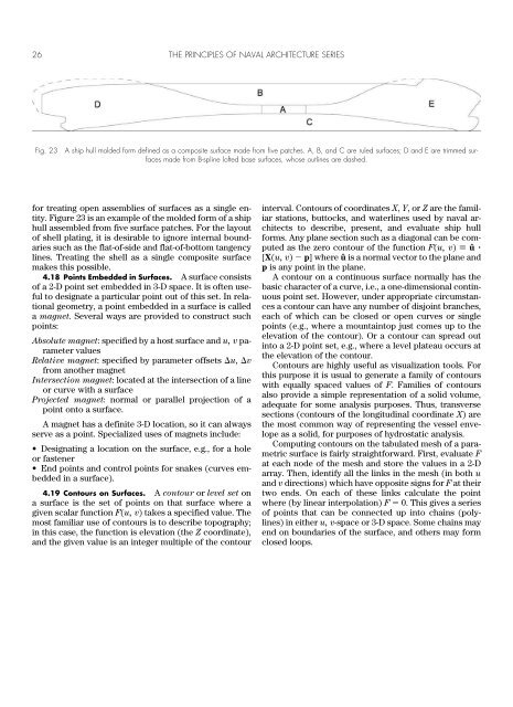
Fig. 23<br />
A ship hull molded form defined as a composite surface made from five patches. A, B, and C are ruled surfaces; D and E are trimmed surfaces<br />
made from B-spline l<strong>of</strong>ted base surfaces, whose outlines are dashed.<br />
for treating open assemblies <strong>of</strong> surfaces as a single entity.<br />
Figure 23 is an example <strong>of</strong> the molded form <strong>of</strong> a ship<br />
hull assembled from five surface patches. For the layout<br />
<strong>of</strong> shell plating, it is desirable to ignore internal boundaries<br />
such as the flat-<strong>of</strong>-side and flat-<strong>of</strong>-bottom tangency<br />
lines. Treating the shell as a single composite surface<br />
makes this possible.<br />
4.18 Points Embedded in Surfaces. A surface consists<br />
<strong>of</strong> a 2-D point set embedded in 3-D space. It is <strong>of</strong>ten useful<br />
to designate a particular point out <strong>of</strong> this set. In relational<br />
geometry, a point embedded in a surface is called<br />
a magnet. Several ways are provided to construct such<br />
points:<br />
Absolute magnet: specified by a host surface and u, v parameter<br />
values<br />
Relative magnet: specified by parameter <strong>of</strong>fsets u, v<br />
from another magnet<br />
Intersection magnet: located at the intersection <strong>of</strong> a line<br />
or curve with a surface<br />
Projected magnet: normal or parallel projection <strong>of</strong> a<br />
point onto a surface.<br />
A magnet has a definite 3-D location, so it can always<br />
serve as a point. Specialized uses <strong>of</strong> magnets include:<br />
• Designating a location on the surface, e.g., for a hole<br />
or fastener<br />
• End points and control points for snakes (curves embedded<br />
in a surface).<br />
4.19 Contours on Surfaces. A contour or level set on<br />
a surface is the set <strong>of</strong> points on that surface where a<br />
given scalar function F(u, v) takes a specified value. <strong>The</strong><br />
most familiar use <strong>of</strong> contours is to describe topography;<br />
in this case, the function is elevation (the Z coordinate),<br />
and the given value is an integer multiple <strong>of</strong> the contour<br />
interval. Contours <strong>of</strong> coordinates X, Y, or Z are the familiar<br />
stations, buttocks, and waterlines used by naval architects<br />
to describe, present, and evaluate ship hull<br />
forms. Any plane section such as a diagonal can be computed<br />
as the zero contour <strong>of</strong> the function F(u, v) û <br />
[X(u, v) p] where û is a normal vector to the plane and<br />
p is any point in the plane.<br />
A contour on a continuous surface normally has the<br />
basic character <strong>of</strong> a curve, i.e., a one-dimensional continuous<br />
point set. However, under appropriate circumstances<br />
a contour can have any number <strong>of</strong> disjoint branches,<br />
each <strong>of</strong> which can be closed or open curves or single<br />
points (e.g., where a mountaintop just comes up to the<br />
elevation <strong>of</strong> the contour). Or a contour can spread out<br />
into a 2-D point set, e.g., where a level plateau occurs at<br />
the elevation <strong>of</strong> the contour.<br />
Contours are highly useful as visualization tools. For<br />
this purpose it is usual to generate a family <strong>of</strong> contours<br />
with equally spaced values <strong>of</strong> F. Families <strong>of</strong> contours<br />
also provide a simple representation <strong>of</strong> a solid volume,<br />
adequate for some analysis purposes. Thus, transverse<br />
sections (contours <strong>of</strong> the longitudinal coordinate X) are<br />
the most common way <strong>of</strong> representing the vessel envelope<br />
as a solid, for purposes <strong>of</strong> hydrostatic analysis.<br />
Computing contours on the tabulated mesh <strong>of</strong> a parametric<br />
surface is fairly straightforward. First, evaluate F<br />
at each node <strong>of</strong> the mesh and store the values in a 2-D<br />
array. <strong>The</strong>n, identify all the links in the mesh (in both u<br />
and v directions) which have opposite signs for F at their<br />
two ends. On each <strong>of</strong> these links calculate the point<br />
where (by linear interpolation) F 0. This gives a series<br />
<strong>of</strong> points that can be connected up into chains (polylines)<br />
in either u, v-space or 3-D space. Some chains may<br />
end on boundaries <strong>of</strong> the surface, and others may form<br />
closed loops.