

The Geometry of Ships

Create successful ePaper yourself
Turn your PDF publications into a flip-book with our unique Google optimized e-Paper software.
THE GEOMETRY OF SHIPS 31<br />
This is <strong>of</strong>ten called an “<strong>of</strong>fsets” representation. Offsets<br />
are also a suitable representation <strong>of</strong> form for some types<br />
<strong>of</strong> seakeeping and resistance analyses, primarily those<br />
based on quasi-2-D “strip theory” or “slender body theory”<br />
approximations (Fig. 27).<br />
Contours are a simple and compact solid representation,<br />
but obviously they provide very limited detail unless<br />
contour intervals are small and points are densely<br />
distributed. <strong>The</strong>y do not lend themselves to rendering as<br />
a solid. <strong>The</strong>y are best suited for elongated shapes, where<br />
the surfaces have small slopes with respect to the longitudinal<br />
axis, and where the solid being represented has<br />
no relevant internal structure.<br />
7.1.3 Polyhedral Models. A polyhedron is a solid<br />
bounded by planar faces. <strong>The</strong> representation can be, for<br />
example, a list <strong>of</strong> 3-D points (vertices) and a list <strong>of</strong> faces,<br />
each face being a list <strong>of</strong> vertices which form a closed planar<br />
polygon. Triangle meshes, where each face is a triangle,<br />
are a commonly used special case. Triangles have<br />
the advantage <strong>of</strong> being automatically planar; this is not<br />
generally true <strong>of</strong> the quadrilateral “panels” formed by the<br />
tabulated mesh <strong>of</strong> a parametric surface.<br />
A polyhedral mesh, especially a triangle mesh, is easy<br />
to render as a solid. Watertight triangular meshes are<br />
widely used for computer-aided manufacturing such as<br />
stereolithography, communicated by STL files. Polyhedral<br />
models are limited for representing smooth curved surfaces,<br />
which require fine subdivision if they are not to appear<br />
faceted (Fig. 28).<br />
7.1.4 Parametric Solids. Parametric solids are an<br />
extension <strong>of</strong> the concept <strong>of</strong> the parametric curve x(t)<br />
and the parametric surface x(u, v) to one more dimension.<br />
A parametric solid is described by a 3-D vector<br />
function <strong>of</strong> three dimensionless parameters: x(u, v, w).<br />
Each parameter has a nominal range, e.g., [0, 1]. Under<br />
moderate conditions on the function x, as a moving<br />
point assumes all values in the 3-D parameter space [0,<br />
1] [0, 1] [0, 1], it sweeps out a 3-D solid in physical<br />
space. Each <strong>of</strong> the six faces <strong>of</strong> the solid is a parametric<br />
surface in two <strong>of</strong> the parameters.<br />
A simple but <strong>of</strong>ten useful example is a ruled solid between<br />
two surfaces x 1 (u, v) and x 2 (u, v):<br />
x(u, v, w) (1 w) x 1 (u, v) wx 2 (u, v) (45)<br />
For example, if x 1 is the hull outer surface and x 2 is<br />
an <strong>of</strong>fset surface a uniform distance inside x 1 , the ruled<br />
solid between them represents the shell as a finitethickness<br />
solid. A 3-D mesh in this solid made by uniformly<br />
subdividing the u, v, and possibly w parameters<br />
creates a set <strong>of</strong> curvilinear finite elements suitable for<br />
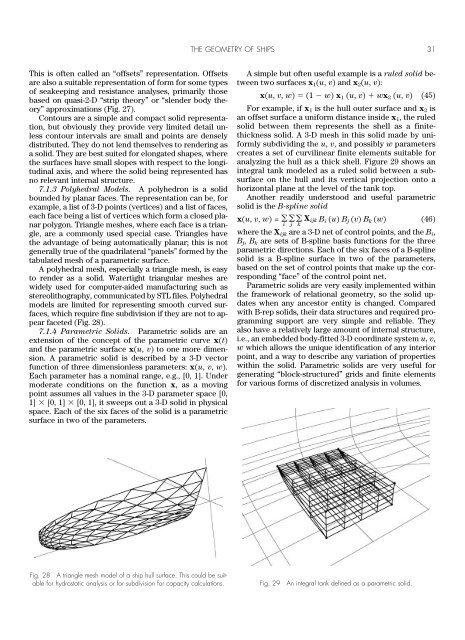
analyzing the hull as a thick shell. Figure 29 shows an<br />
integral tank modeled as a ruled solid between a subsurface<br />
on the hull and its vertical projection onto a<br />
horizontal plane at the level <strong>of</strong> the tank top.<br />
Another readily understood and useful parametric<br />
solid is the B-spline solid<br />
x(u, v, w) = <br />
i<br />
<br />
j<br />
X ijk B i (u) B j (v) B k (w) (46)<br />
k<br />
where the X ijk are a 3-D net <strong>of</strong> control points, and the B i ,<br />
B j , B k are sets <strong>of</strong> B-spline basis functions for the three<br />
parametric directions. Each <strong>of</strong> the six faces <strong>of</strong> a B-spline<br />
solid is a B-spline surface in two <strong>of</strong> the parameters,<br />
based on the set <strong>of</strong> control points that make up the corresponding<br />
“face” <strong>of</strong> the control point net.<br />
Parametric solids are very easily implemented within<br />
the framework <strong>of</strong> relational geometry, so the solid updates<br />
when any ancestor entity is changed. Compared<br />
with B-rep solids, their data structures and required programming<br />
support are very simple and reliable. <strong>The</strong>y<br />
also have a relatively large amount <strong>of</strong> internal structure,<br />
i.e., an embedded body-fitted 3-D coordinate system u, v,<br />
w which allows the unique identification <strong>of</strong> any interior<br />
point, and a way to describe any variation <strong>of</strong> properties<br />
within the solid. Parametric solids are very useful for<br />
generating “block-structured” grids and finite elements<br />
for various forms <strong>of</strong> discretized analysis in volumes.<br />
Fig. 28 A triangle mesh model <strong>of</strong> a ship hull surface. This could be suitable<br />
for hydrostatic analysis or for subdivision for capacity calculations. Fig. 29 An integral tank defined as a parametric solid.