

The Geometry of Ships

Create successful ePaper yourself
Turn your PDF publications into a flip-book with our unique Google optimized e-Paper software.
50 THE PRINCIPLES OF NAVAL ARCHITECTURE SERIES<br />
An exception to positive initial stability occurs sometimes<br />
in unconventional high-speed craft which are<br />
partially or completely supported by dynamic lift at operating<br />
speed. <strong>The</strong> geometric requirements on form for<br />
high-speed operation may dictate a shape with negative<br />
initial stability; such a vessel is said to “loll” to one side<br />
or the other when floating at rest.<br />
Sailing vessels require substantial roll stability to<br />
counter the steady heeling moments associated with<br />
wind force on their sails, and the opposing hydrodynamic<br />
forces on hull and appendages. Roll stability is<br />
therefore a crucial factor in sailing performance, and<br />
many features <strong>of</strong> sailing yacht design have the purpose<br />
<strong>of</strong> enhancing it: shallow, beamy hull forms, deep draft,<br />
concentration <strong>of</strong> weight in deeply placed ballast, weight<br />
savings in hull, deck, and rigging, and multihull configurations.<br />
It is not initial stability that counts, <strong>of</strong> course,<br />
but rather righting moment available at operating heel<br />
angles; however, for conventional monohull designs, the<br />
initial stability is a good indicator <strong>of</strong> sail-carrying power.<br />
Some <strong>of</strong> the highest-performance sailing craft, trimarans,<br />
can have negative initial stability.<br />
11.1.7 Longitudinal Metacenter. Analysis <strong>of</strong> longitudinal<br />
stability is highly analogous to that <strong>of</strong> transverse<br />
stability. From equation (123),<br />
dM / d pg (z M l z G ) GM L (124)<br />
where z M l z B I yy /, the longitudinal height <strong>of</strong> metacenter,<br />
and GM L is the longitudinal metacentric height.<br />
<strong>The</strong> geometric term I yy / is longitudinal metacentric<br />
radius. Note that I yy is the moment <strong>of</strong> inertia <strong>of</strong> the waterplane<br />
about a transverse axis through the center <strong>of</strong> flotation<br />
C F . If moment <strong>of</strong> inertia I YY is calculated with respect<br />
to some other transverse axis, the parallel-axis theorem<br />
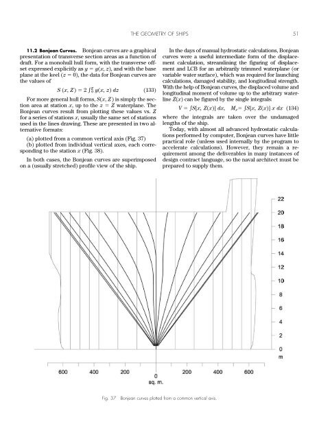
must be used to transform to the center <strong>of</strong> flotation:<br />
I yy I YY A wp xF 2 (125)<br />
Normally, longitudinal stability is not a large design<br />
issue because <strong>of</strong> the elongated form <strong>of</strong> most vessels. It<br />
can be used operationally to predict the effect <strong>of</strong> longitudinal<br />
weight movements and loading on the trim angle.<br />
This can be expressed as moment to change trim 1 cm:<br />
MT1cm GM L /(100L) (126)<br />
11.1.8 Wetted Surface. For a vessel floating on a<br />
specified waterline, the total area <strong>of</strong> its outer surface in<br />
contact with the water is known as its wetted surface. As<br />
this is an area, its units are length squared. Wetted surface<br />
is <strong>of</strong> interest for powering and speed prediction; the<br />
frictional component <strong>of</strong> resistance is ordinarily assumed<br />
to be in direct proportion to wetted surface area. It also<br />
indicates the quantity <strong>of</strong> antifouling paint required to<br />
coat the vessel up to this waterline. Wetted surface is<br />
<strong>of</strong>ten included in the curves <strong>of</strong> form.<br />
<strong>The</strong> calculation <strong>of</strong> area for a parametric surface has<br />
been outlined in Section 4.2, in terms <strong>of</strong> the components<br />
<strong>of</strong> the metric tensor. This calculation is fairly straightforward,<br />
though a complication is that the wetted surface is<br />
usually only a portion <strong>of</strong> the complete parametric hull<br />
surface, so the domain <strong>of</strong> integration in u, v space will<br />
have a complex boundary which has to be computed by<br />
intersecting the surface with a plane. In relational geometry,<br />
it is convenient to create a subsurface or trimmed<br />
surface (portion <strong>of</strong> a surface bounded by snakes, one <strong>of</strong><br />
which can be an intersection snake along the waterline)<br />
representing the wetted surface; this can be arranged to<br />
update automatically as the draft is varied.<br />
Traditionally, wetted surface is calculated as the sum<br />
<strong>of</strong> area elements over the hull surface, a double integral<br />
with integration over x done last. <strong>The</strong> integral is not in a<br />
form that can be reduced by Gauss’ theorem, so the integrand<br />
turns out to be relatively complex compared with<br />
most <strong>of</strong> the integrals required for hydrostatics. On a symmetric<br />
hull, we can locate any given point X on the hull<br />
by two coordinates:<br />
(a) x the usual longitudinal coordinate<br />
(b) s arc length measured from the centerline along<br />
the intersection <strong>of</strong> the hull with the transverse plane<br />
through x.<br />
In terms <strong>of</strong> these (dimensional) parameters, the surface<br />
point is described as X {x, y(x, s), z(x, s)}, and the<br />
first derivatives are X x {1, y x , z x } and X s {0, y s , z s },<br />
where subscripts x and s stand for partial derivatives.<br />
<strong>The</strong> metric tensor components (equation 33) are<br />
g 11 1 y 2 x z 2 x (127)<br />
g 12 y x y s z x z s (128)<br />
g 22 y 2 s z 2 s 1 (129)<br />
(the last because s is defined as arc length in the transverse<br />
plane), so the metric tensor discriminant becomes:<br />
g 1 (y x z s z x y s ) 2 (130)<br />
This can be expressed in terms <strong>of</strong> the components <strong>of</strong><br />
the unit normal n {y x z s z x y s , z s , y s }/ g as: g 1<br />
nxg 2 and solving for g: g 1/(1 nx) 2 sec 2 , where is<br />
the bevel angle with respect to the x axis. Thus the wetted<br />
surface area is<br />
WS g dx ds sec ds dx (131)<br />
<strong>The</strong> sec factor is termed obliquity. For a sufficiently<br />
slender hull, n x is everywhere small and sec will not<br />
differ appreciably from 1. <strong>The</strong>n the wetted surface is (approximately)<br />
simply WS G(x)dx, where G(x) is wetted<br />
girth at station x.<br />
Wetted surface does not transform in any simple way<br />
under affine stretching. Under a geosim transformation,<br />
being an area, it varies simply as 2 .<br />
Wetted surface is conventionally nondimensionalized<br />
with a combination <strong>of</strong> length and displacement to make<br />
the wetted surface coefficient:<br />
C WS WS/L (132)<br />
where is displacement volume and L is length. Values<br />
<strong>of</strong> C WS range from about 2.6 to 2.9 for usual ships <strong>of</strong> normal<br />
form at design flotation.