

The Geometry of Ships

Create successful ePaper yourself
Turn your PDF publications into a flip-book with our unique Google optimized e-Paper software.
54 THE PRINCIPLES OF NAVAL ARCHITECTURE SERIES<br />
Fig. 39<br />
Ship topsides and superstructure designed for low radar detectability.<br />
<strong>of</strong>f all three surfaces returns it exactly parallel to its arrival<br />
direction, producing a large cross section over a<br />
wide range <strong>of</strong> directions.)<br />
Superstructures for yachts reflect styling as well as<br />
function, and <strong>of</strong>ten consist <strong>of</strong> elaborately sculptured surface<br />
elements, <strong>of</strong>ten with far more complex geometry<br />
than the hulls. Location and shapes <strong>of</strong> windows is an important<br />
styling aspect <strong>of</strong> superstructure design. For exterior<br />
rendered views it is effective to model a window as<br />
a black or dark blue surface element.<br />
12.4 Hull Appendages. <strong>The</strong> most common hull appendages<br />
for ships are bow bulbs, stern tube bossings,<br />
sonar domes, bilge keels, and rudders. Though in each<br />
case there is a possibility <strong>of</strong> integrating the appendage<br />
with the hull surface (and admitting there are going to be<br />
borderline cases where it is difficult to decide whether<br />
to add on or to integrate), it is <strong>of</strong>ten far more convenient<br />
to leave the main hull surface alone and retr<strong>of</strong>it it by attaching<br />
the appendage as a separate surface.<br />
For example, Fig. 40(a) shows a B-spline surface for<br />
the forebody <strong>of</strong> a destroyer, using a 5 5 net <strong>of</strong> control<br />
points. In Fig. 40(b), five rows and five columns <strong>of</strong> additional<br />
control points have been inserted in order to provide<br />
enough control points in the forefoot area to form<br />
an integrated sonar dome; the dome is shown in Fig.<br />
40(c). However, there are now some 30 superfluous control<br />
points in the bottom and stem regions, and it will be<br />
very difficult to position them all in such a way as to obtain<br />
anything like the fairness <strong>of</strong> the original simple surface<br />
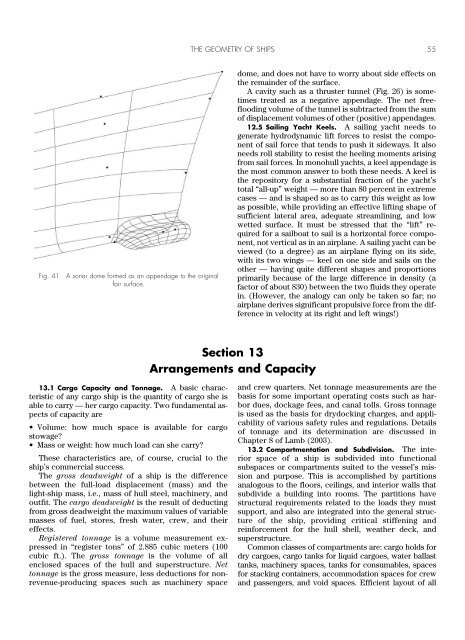
in these areas. Figure 41 shows the alternative <strong>of</strong><br />
treating the sonar dome as the appendage that it is.<br />
Outside a well-defined line on the hull (a snake), the hull<br />
surface is unaffected by the presence <strong>of</strong> the dome. <strong>The</strong><br />
dome designer is then free to focus on the shape <strong>of</strong> the<br />
a<br />
b<br />
C<br />
Fig. 40 Sonar dome at the forefoot <strong>of</strong> a hull, formed as an integral<br />
part <strong>of</strong> the B-spline hull surface by addition <strong>of</strong> rows and columns <strong>of</strong><br />
control points.