

The Geometry of Ships

You also want an ePaper? Increase the reach of your titles
YUMPU automatically turns print PDFs into web optimized ePapers that Google loves.
THE GEOMETRY OF SHIPS 47<br />
Define the nominal lengths <strong>of</strong> the three parent<br />
bodies as:<br />
L 1 X 1 X 0 , L 2 X 2 X 1 , L 3 X 3 X 2 ;<br />
their waterline lengths as:<br />
W 1 1 L 1 , W 2 L 2 , W 3 3 L 3 ;<br />
their displacement volumes as:<br />
V 1 , V 2 , V 3 ;<br />
and their centers <strong>of</strong> buoyancy as:<br />
1 L 1 , X 1 0.5L 2 , X 2 3 L 3 .<br />
( 1 , 3 , 1 , and 3 are all constants that depend on the<br />
original ship geometry.)<br />
Now apply longitudinal affine stretching factors 1 ,<br />
2 , 3 to the three bodies, and reassemble them into a<br />
complete candidate ship. <strong>The</strong> result <strong>of</strong> this construction<br />
is a triply infinite family <strong>of</strong> candidate ship forms, with 1 ,<br />
2 , 3 as parameters. (<strong>The</strong> parent ship is 1 1, 2 1,<br />
3 1.) To determine these parameters, we will impose<br />
an equal number <strong>of</strong> conditions (form parameters):<br />
• Displacement volume, T<br />
• Longitudinal center <strong>of</strong> buoyancy (as a fraction <strong>of</strong> waterline),<br />
T<br />
• Prismatic coefficient, C pT .<br />
(<strong>The</strong> subscript T stands for “target.”)<br />
Next, we need a way to evaluate the form coefficients<br />
as functions <strong>of</strong> 1 , 2 , 3 . <strong>The</strong> properties <strong>of</strong> affine transformation<br />
make this easy. First, the waterline length W<br />
is the sum <strong>of</strong> the body waterlines:<br />
W 1 1 L 1 2 L 2 3 3 L 3 (114)<br />
Displacement volume is the sum <strong>of</strong> the three body<br />
volumes:<br />
T 1 V 1 2 V 2 3 V 3 (115)<br />
Likewise, the x-moment <strong>of</strong> displacement volume is<br />
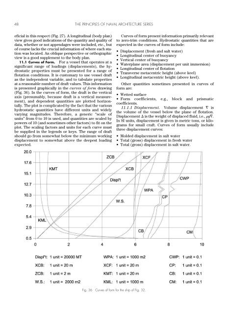
the sum <strong>of</strong> the body volumes, each multiplied by the X-<br />
coordinates <strong>of</strong> its respective centroid:<br />
M X 1 V 1 [ 1 1 L 1 ]<br />
2 V 2 [ 1 L 1 0.5 2 L 2 ]<br />
3 V 3 [ 1 L 1 2 L 2 3 3 L 3 ]<br />
T T W (116)<br />
<strong>The</strong> prismatic coefficient is:<br />
C pT = T / [A ms W] (117)<br />
where A ms is the midship section area.<br />
Equations (115, 116, 117) are three simultaneous<br />
equations in the three unknowns 1 , 2 , 3 . (Note that in<br />
general, the equations are likely to be nonlinear, though<br />
in this case all but equation (116) can be arranged in linear<br />
form.)<br />
Such a system <strong>of</strong> simultaneous nonlinear equations<br />
can be attacked with the Newton-Raphson method<br />
(Kreyszig 1979; Press, Flannery, Teukolsky & Vetterling<br />
1988). With any luck, this will provide an efficient and accurate<br />
solution. Some numerical pitfalls should be noted.<br />
When the equations are nonlinear, there is no guarantee<br />
that a solution exists; even when they are linear, there is<br />
no guarantee <strong>of</strong> a unique solution. Convergence to a solution<br />
can depend on the values used to start the iteration.<br />
In this example, a solution with any <strong>of</strong> the ’s less<br />
than zero would not be a meaningful result.<br />
A form parameter-based system can also be built<br />
around a general optimization algorithm (Kreyszig<br />
1979; Press, Flannery, Teukolsky & Vetterling 1988),<br />
which seeks to minimize some objective function such<br />
as predicted resistance at a specified operating speed,<br />
or an average surface fairness measure, with equality or<br />
inequality constraints stated in terms <strong>of</strong> various form<br />
parameters.<br />
During the design <strong>of</strong> a vessel, the methods <strong>of</strong> hydrostatic<br />
analysis detailed in Section 9 are applied to tabulate and<br />
graph various hydrostatic properties. This information is<br />
used throughout the design process to assess the hydrostatic<br />
equilibrium and stability. If the vessel is subject to<br />
classification, hydrostatic properties must be submitted<br />
as part <strong>of</strong> that procedure. Further, hydrostatic properties<br />
will be communicated to the owner/operator <strong>of</strong> the vessel<br />
to be utilized during loading and operation. In the<br />
eventuality <strong>of</strong> a collision or grounding, knowledge <strong>of</strong> hydrostatic<br />
properties may be crucial in the conduct and<br />
success <strong>of</strong> salvage operations. Because the data will be<br />
Section 11<br />
Upright Hydrostatic Analysis<br />
used for several functions beyond the design <strong>of</strong>fice, it is<br />
important that it be developed and furnished in a more or<br />
less conventional and agreed-upon format. Such formats<br />
are well established for conventional vessel types. In the<br />
case <strong>of</strong> an unconventional vessel, it may be a challenge to<br />
decide on a relevant set <strong>of</strong> hydrostatic properties, and to<br />
present them in such a way that users <strong>of</strong> the information<br />
can relate them to the standard conventions.<br />
<strong>The</strong> input to the hydrostatic calculation is in most<br />
cases a form <strong>of</strong> <strong>of</strong>fsets on transverse stations, represented<br />
in a computer file. It is important to document the<br />
actual <strong>of</strong>fsets used. Graphic views <strong>of</strong> the <strong>of</strong>fsets are ben-