

The Geometry of Ships

You also want an ePaper? Increase the reach of your titles
YUMPU automatically turns print PDFs into web optimized ePapers that Google loves.
30 THE PRINCIPLES OF NAVAL ARCHITECTURE SERIES<br />
Curves <strong>of</strong> intersection arising from the intersections<br />
between two surfaces can be recognized as snakes residing<br />
on both <strong>of</strong> the surfaces. <strong>The</strong> difficulties that can be<br />
present in computing such intersections have been discussed<br />
above in Section 4.15.<br />
6.2 Applications <strong>of</strong> Curves on Surfaces. Curves on surfaces<br />
can play several roles in definition <strong>of</strong> ship geometry:<br />
• As decorative lines; e.g., cove stripe, boot stripe, hull<br />
decorations<br />
• As boundaries <strong>of</strong> subsurfaces and trimmed surfaces;<br />
e.g., delineating subdivision <strong>of</strong> the hull surface into shell<br />
plates for fabrication<br />
• As a junction between surfaces; e.g., the deck-at-side<br />
curve drawn on the hull and used as an edge curve for<br />
the weather deck surface<br />
• As a trace for a linear feature to be constructed on another<br />
surface; e.g., a guard, strake, or bilge keel<br />
• As alignment marks to be carried through a plate expansion<br />
process.<br />
Section 7<br />
<strong>Geometry</strong> <strong>of</strong> Solids<br />
<strong>The</strong> history <strong>of</strong> geometric modeling in engineering<br />
design has progressed from “wireframe” models representing<br />
curves only, to surface modeling, to solid modeling.<br />
Along with the increase in dimensionality, there<br />
is a concomitant increase in the level <strong>of</strong> complexity <strong>of</strong><br />
representation. Wireframe and surface models have<br />
gone a long way toward systematizing and automating<br />
design and manufacturing, but ultimately most articles<br />
that are manufactured, including ships and their components,<br />
are 3-D solids, and there are fundamental<br />
benefits in treating them as such. Wireframe representations<br />
were the dominant technology <strong>of</strong> the 1970s; surface<br />
modeling became well developed during the 1980s;<br />
during the 1990s the focus shifted to solid models as<br />
computer speed and storage improved to handle the<br />
higher level <strong>of</strong> complexity, and as the underlying mathematical,<br />
algorithmic, and computational tools required<br />
to support solids were further developed.<br />
We will first briefly review a number <strong>of</strong> alternative<br />
representations <strong>of</strong> solids, each <strong>of</strong> which has some advantages<br />
and some limited applications. Of these, boundary<br />
representation or B-rep solids have emerged as the most<br />
successful and versatile solid modeling technology, and<br />
they will therefore be the focus <strong>of</strong> this section.<br />
7.1 Various Solid Representations.<br />
7.1.1 Volume Elements (Voxels). A conceptually<br />
simple solid representation is to divide space into a 3-D<br />
rectangular array (lattice) <strong>of</strong> individual cubic volume elements<br />
or voxels, and then characterize the contents <strong>of</strong><br />
each voxel within a domain <strong>of</strong> interest. This is a 3-D extension<br />
<strong>of</strong> the way 2-D images are represented as arrays<br />
<strong>of</strong> picture elements or “pixels.” For a homogeneous<br />
solid, the voxel information can be as little as one bit,<br />
i.e., is this voxel occupied by material, or is it empty? Or,<br />
if a complex inhomogeneous solid is being described,<br />
numerous attributes can be attached to each voxel; e.g.,<br />
density, temperature, concentration <strong>of</strong> various chemical<br />
species, etc.<br />
Voxels are most useful for medium-resolution descriptions<br />
<strong>of</strong> inhomogeneous solids with significant internal<br />
structure. <strong>The</strong> storage requirements and processing<br />
effort are high, and increase as the cube <strong>of</strong> the<br />
resolution. For example, a voxel description <strong>of</strong> the<br />
human body at a resolution <strong>of</strong> 1 mm requires on the<br />
order <strong>of</strong> 10 8 voxels (and <strong>of</strong> course, 1 mm is still a very<br />
coarse resolution for describing most tissues and<br />
anatomical structures).<br />
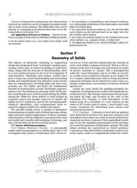
7.1.2 Contours. Contours or level sets on surfaces<br />
were described in Section 4.19, and were related to the<br />
description <strong>of</strong> an object as a solid. In naval architecture,<br />
transverse sections (contours <strong>of</strong> the longitudinal coordinate<br />
X) are the standard representation <strong>of</strong> the envelope<br />
<strong>of</strong> a vessel for purposes <strong>of</strong> hydrostatic analysis. <strong>The</strong> individual<br />
sections are represented as closed polylines.<br />
Contours are also used within a hydrostatic model to describe<br />
tanks, voids, or compartments inside the vessel.<br />
Fig. 27<br />
Offsets representation <strong>of</strong> a ship as a solid cut by contours (X constant).