

The Geometry of Ships

You also want an ePaper? Increase the reach of your titles
YUMPU automatically turns print PDFs into web optimized ePapers that Google loves.
THE GEOMETRY OF SHIPS 53<br />
Section 12<br />
Decks, Bulkheads, Superstructures, and Appendages<br />
Although the hull <strong>of</strong> a ship accounts for its largest surfaces,<br />
and <strong>of</strong>ten the most complex and demanding surfaces<br />
in terms <strong>of</strong> shape requirements, other parts <strong>of</strong> the<br />
ship also present many geometric challenges. Decks and<br />
bulkheads are typically relatively simple surfaces (planar<br />
in most cases), but need complex outlines in order to<br />
meet the hull accurately. Superstructures are <strong>of</strong>ten complex<br />
assemblages <strong>of</strong> many large and small surface elements,<br />
with important aesthetic and functional requirements.<br />
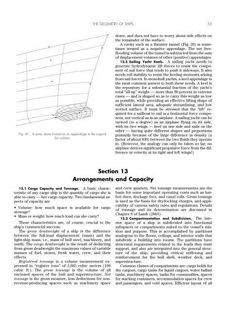
Hull appendages — for example, stern tube<br />
bossings, bow bulbs, sonar domes, and sailing yacht<br />
keels — must be shaped to perform critical hydrodynamic<br />
functions, and require accurate, usually smooth,<br />
connection to the hull surfaces.<br />
12.1 Interior Decks and Bulkheads. Interior decks<br />
and bulkheads are typically horizontal or vertical planes,<br />
trimmed by intersection with the hull. <strong>The</strong> longitudinal<br />
subdivision by watertight bulkheads has to meet hydrostatic<br />
requirements for damaged flotation and stability.<br />
<strong>The</strong> bulkheads and/or interior decks also form the principal<br />
compartmentation <strong>of</strong> the ship’s interior, so their locations<br />
interact with requirements for locating machinery<br />
and cargo. It is highly beneficial in the early stages <strong>of</strong><br />
design for the bulkhead and deck positions to be parametrically<br />
variable, to support optimal resolution <strong>of</strong><br />
these space and volume requirements.<br />
12.2 Weather Deck. Weather deck surfaces are<br />
occasionally planes — horizontal or with some fore-andaft<br />
inclination — but are much more commonly given<br />
camber (transverse shape) in order to encourage shedding<br />
<strong>of</strong> water, to gain structural stiffness, and to gain interior<br />
volume without increase <strong>of</strong> freeboard. In small<br />
craft, it is common for the deck camber to be specified<br />
as a circular arc having a constant ratio <strong>of</strong> crown to<br />
breadth, typically 6 to 8 percent. <strong>The</strong> relationship between<br />
radius R, crown h, and chord c (i.e., breadth for a<br />
deck) for a circular arc is<br />
2Rh h 2 c 2 /4 (135)<br />
This shows that for constant h/c, R is directly proportional<br />
to c:<br />
R/c (c/h)/8 (h/c)/2 (136)<br />
If the weather deck is required to be developable, this<br />
imposes substantial constraints on the design. A general<br />
cylinder swept by translation <strong>of</strong> a camber pr<strong>of</strong>ile along a<br />
longitudinal straight line is the simplest solution; however,<br />
this tends to make a very flat deck forward, where<br />
it becomes narrow. A shallow cone made from the deck<br />
perimeter curves, with its apex inside the superstructure,<br />
is <strong>of</strong>ten an advantageous construction.<br />
Large commercial ships usually have planar deck surfaces,<br />
the outboard portions slanted a few degrees, combined<br />
with some width <strong>of</strong> flat deck near the centerline.<br />
12.3 Superstructures. In merchant and military<br />
ships, superstructures usually consist <strong>of</strong> flat surfaces,<br />
making for relatively easy geometric constructions from<br />
trimmed planes and flat quadrilateral or triangular<br />
patches. Where the superstructure meets the deck, some<br />
plane intersections with deck surfaces, or projections<br />
onto the deck, will be required.<br />
An interesting recent trend in military ship design is<br />
the “stealth” concept for reducing detectability by radar.<br />
Since its invention during World War II, radar has been an<br />
extremely important military technology. <strong>The</strong> basic concept<br />
<strong>of</strong> radar is to scan a region <strong>of</strong> interest with a focused<br />
beam <strong>of</strong> pulsed high-frequency radio waves (wavelength<br />
<strong>of</strong> a few mm or cm) and listen for reflected pulses<br />
(echoes) at the same or nearby wavelengths. <strong>The</strong> orientation<br />
<strong>of</strong> the antenna at the time reflection is received gives<br />
the direction <strong>of</strong> the reflecting object, and the time delay<br />
between emission and reception <strong>of</strong> the pulse provides the<br />
range (distance). In addition, measuring the frequency<br />
shift <strong>of</strong> the returned signal indicates the target’s velocity<br />
component along the beam direction.<br />
“Radar cross-section,” a quantity with units <strong>of</strong> area, is a<br />
standard way to express the radar reflectivity <strong>of</strong> an object.<br />
Essentially, it is the area <strong>of</strong> a perfect reflector oriented exactly<br />
normal to the radar beam, that would return a signal<br />
<strong>of</strong> the same strength as the object. Radar cross-section is<br />
highly dependent on the exterior geometry <strong>of</strong> the object,<br />
and on its orientation with respect to the radar beam.<br />
One component <strong>of</strong> stealth technology is naturally the<br />
development <strong>of</strong> materials and coatings that are effective<br />
absorbers <strong>of</strong> electromagnetic radiation at radar frequencies.<br />
Another important component is purely geometric:<br />
the use, ins<strong>of</strong>ar as possible, <strong>of</strong> flat faces for the ship’s exterior<br />
surface, angled so as to reflect radar away from<br />
the transmitter’s direction (Fig. 39). Whereas a curved<br />
surface presents a moderate cross-section over a range<br />
<strong>of</strong> angular directions, a flat face produces a comparatively<br />
very high cross-section, but only in one very specific<br />
direction — the direction <strong>of</strong> the normal to the face.<br />
<strong>The</strong> use <strong>of</strong> flat faces trades <strong>of</strong>f very large cross-sections<br />
in a few particular directions against near-total invisibility<br />
from all other directions. Since the majority <strong>of</strong> radar<br />
sources directed at a ship will be close to sea level, the<br />
horizontal directions are most important; this consideration<br />
promotes use <strong>of</strong> faces that are inclined inboard 10°<br />
to 15° from vertical, allowing for moderate roll angles.<br />
This inclination also avoids 90° concave corners, e.g., between<br />
the superstructure and the deck, where double reflections<br />
provide a strong return in any direction normal<br />
to the line <strong>of</strong> intersection between the two planes.<br />
(A concave corner where three mutually orthogonal<br />
planes meet is particularly to be avoided; this makes the<br />
well-known “corner reflector” configuration used, for<br />
example, on navigational buoys. Triple reflection <strong>of</strong> a ray