

VGB POWERTECH 5 (2021) - International Journal for Generation and Storage of Electricity and Heat
VGB PowerTech - International Journal for Generation and Storage of Electricity and Heat. Issue 5 (2021). Technical Journal of the VGB PowerTech Association. Energy is us! Nuclear power. Nuclear power plants - operation and operation experiences
VGB PowerTech - International Journal for Generation and Storage of Electricity and Heat. Issue 5 (2021).
Technical Journal of the VGB PowerTech Association. Energy is us!
Nuclear power. Nuclear power plants - operation and operation experiences

You also want an ePaper? Increase the reach of your titles
YUMPU automatically turns print PDFs into web optimized ePapers that Google loves.
Residual <strong>Heat</strong> Removal Line (Redundancy)<br />
<strong>VGB</strong> PowerTech 5 l <strong>2021</strong><br />
Safety-related residual heat removal chains <strong>for</strong> pressure water reactors<br />
Development <strong>of</strong> safety-related residual<br />
heat removal chains from german<br />
technology pressure water reactors<br />
(light <strong>and</strong> heavy water)<br />
Franz Stuhlmüller <strong>and</strong> Rafael Macián-Juan<br />
Kurzfassung<br />
Entwicklung von sicherheitstechnischen<br />
Nachwärmeabfuhrpfaden für<br />
Druckwasserreaktoren deutscher<br />
Technologie (Leicht- und Schwerwasser)<br />
Die auf Entwicklungen in Deutschl<strong>and</strong> basierenden<br />
Druckwasserreaktor-KKW für angereicherten<br />
Brennst<strong>of</strong>f (PLWR) einerseits und für<br />
Natururan (PHWR) <strong>and</strong>ererseits sind in ihrer<br />
Basiskonzeption weitgehend identisch. Ein<br />
markanter Unterschied besteht jedoch im Umfang<br />
der Reaktorhauptsysteme. Während diese<br />
beim PLWR nur aus dem Reaktorkühl- und dessen<br />
Druckhalte- und Abblasesystem bestehen,<br />
kommt beim PHWR noch das Moderatorsystem<br />
hinzu, das im Leistungsbetrieb der Anlage den<br />
Moderator (Schwerwasser) permanent zu kühlen<br />
hat. Dieses verfahrenstechnische System<br />
wird in Zweitfunktion als innerstes Glied der<br />
sicherheitstechnisch wichtigen Nachkühlkette<br />
zur Wärmeabfuhr nach dem Abschalten des Reaktors<br />
verwendet. Während man beim PLWR –<br />
auch für die neuesten Anlagen – sowohl zum<br />
Abkühlen nach planmäßiger Abschaltung als<br />
auch zur Beherrschung der überwiegenden<br />
Zahl anzunehmender Störfalle in der ersten<br />
Zeit nach Schadenseintritt auf die weitere Bespeisung<br />
der Dampferzeuger angewiesen ist,<br />
wurde für den PHWR die Möglichkeit geschaffen,<br />
die Reaktorkühlung von Anfang an allein<br />
über die Nachkühlkette durchzuführen.<br />
Anh<strong>and</strong> der Statusprojekte beider Kraftwerkslinien<br />
dokumentieren sich nicht nur deren Einheitengrößen-Wachstum,<br />
sondern auch die<br />
Entwicklungs-Schritte ihrer Nachkühlketten-<br />
Technologie, die hier aufgezeigt wird. l<br />
Authors<br />
Franz Stuhlmüller<br />
External Scientific Associate at the Chair <strong>for</strong><br />
Nuclear Technology<br />
Technical University <strong>of</strong> Munich<br />
Pr<strong>of</strong>. Rafael Macián-Juan, PhD<br />
Head <strong>of</strong> the Chair <strong>of</strong> Nuclear Technology<br />
Technical University <strong>of</strong> Munich<br />
Munich, Germany<br />
Development <strong>of</strong> Safety-related Residual <strong>Heat</strong><br />
Removal Chains from German Technology<br />
Pressure Water Reactors I Franz Stuhlmüller<br />
Introduction<br />
The Nuclear Power Plants (NPPs) with<br />
Pressure Water Reactor <strong>for</strong> enriched fuel<br />
(PLWR, Pressurized Light Water Reactor)<br />
<strong>and</strong> <strong>for</strong> natural uranium (PHWR, Pressurized<br />
Heavy Water Reactor), developed in<br />
Germany, are largely identical in their basic<br />
design. However, there is a striking difference<br />
in the scope <strong>of</strong> the main reactor<br />
systems. While in PLWR these only consist<br />
<strong>of</strong> Reactor <strong>and</strong> Reactor Coolant System including<br />
Pressurizer <strong>and</strong> Pressurizer Relief<br />
Tank, in PHWR the Moderator System is<br />
added. In power operation <strong>of</strong> a PLWR, the<br />
entire thermal reactor power is transferred<br />
to the water/steam cycle via the Steam<br />
Generators. In PHWR, on the other h<strong>and</strong>,<br />
part <strong>of</strong> the power (approx. 10 %) has to be<br />
removed – at a lower temperature level –<br />
from the moderator, which is spatially separated<br />
from the main reactor coolant within<br />
the Reactor Pressure Vessel, but is kept<br />
at the same pressure via function-related<br />
Reactor<br />
2 1 1 1 1<br />
2 2 2<br />
3 3 3 3<br />
4 4 4 4<br />
5 5 5 5<br />
<strong>Heat</strong> Sink<br />
compensating openings. This portion <strong>of</strong><br />
power is used to preheat the feed water be<strong>for</strong>e<br />
it enters the Steam Generators. The<br />
Moderator System installed <strong>for</strong> this purpose<br />
can also be used in a second function<br />
as the inner link in the Residual <strong>Heat</strong> Removal<br />
Chain (RHRC) <strong>for</strong> cooling the reactor<br />
after it has been switched <strong>of</strong>f. In PLWR<br />
the analog system is operated exclusively<br />
<strong>for</strong> the removal <strong>of</strong> residual heat from the<br />
reactor <strong>and</strong>, if necessary, the fuel pool. In<br />
the following, the development <strong>of</strong> the<br />
RHRC <strong>of</strong> both NPP lines is shown <strong>and</strong> the<br />
main differences between both NPP-types<br />
in this regard are explained by comparing<br />
the most recently erected plants, DWR<br />
1,300 MW (KONVOI) <strong>and</strong> Atucha 2.<br />
Residual heat removal chain,<br />
structure <strong>and</strong> terms<br />
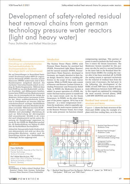
F i g u r e 1 shows the basic structure <strong>of</strong> the<br />
three-part RHRC using the example <strong>of</strong> a<br />
plant with four cooling lines, as is the case<br />
Residual <strong>Heat</strong> Removal Chain<br />
1<br />
2<br />
3<br />
4<br />
5<br />
Residual <strong>Heat</strong> Removal Pump/<br />
Moderator Pump<br />
Residual <strong>Heat</strong> Exchanger/<br />
Moderator Cooler<br />
Component CoolingPump/<br />
RHR Intermediate Cooling Pump<br />
Component Cooling<br />
<strong>Heat</strong> Exchanger/<br />
RHR Intermediate Cooling<br />
<strong>Heat</strong> Exchanger<br />
Secured Service Cooling<br />
Water Pump<br />
Fig. 1. Residual <strong>Heat</strong> Removal from the Reactor; Definition <strong>of</strong> “System” (or “RHR link”),<br />
“Sub-System”, “RHR Line” <strong>and</strong> “RHR Chain”.<br />
49


