

VGB POWERTECH 5 (2021) - International Journal for Generation and Storage of Electricity and Heat
VGB PowerTech - International Journal for Generation and Storage of Electricity and Heat. Issue 5 (2021). Technical Journal of the VGB PowerTech Association. Energy is us! Nuclear power. Nuclear power plants - operation and operation experiences
VGB PowerTech - International Journal for Generation and Storage of Electricity and Heat. Issue 5 (2021).
Technical Journal of the VGB PowerTech Association. Energy is us!
Nuclear power. Nuclear power plants - operation and operation experiences

Create successful ePaper yourself
Turn your PDF publications into a flip-book with our unique Google optimized e-Paper software.
<strong>VGB</strong> PowerTech 5 l <strong>2021</strong><br />
Safety-related residual heat removal chains <strong>for</strong> pressure water reactors<br />
Cooling System*. In this way, heat removal<br />
from the fuel pool is possible in principle<br />
via each <strong>of</strong> the four RHR lines.<br />
NPPs with Pressurized Heavy<br />
Water Reactors (PHWR)<br />
The function <strong>of</strong> the Moderator System in<br />
power operation <strong>of</strong> the plant requires identical<br />
pressure <strong>and</strong> temperature design values<br />
as <strong>for</strong> the Reactor Coolant System itself.<br />
However, this also opens up the possibility<br />
– by switching over valves inside the<br />
Moderator System <strong>and</strong> with an appropriate<br />
design <strong>of</strong> the RHR Intermediate Cooling<br />
System as the middle link <strong>of</strong> the RHRC – to<br />
take over the cooling <strong>of</strong> the reactor immediately<br />
after shut down, even without additional<br />
Steam Generator feed. This option<br />
has not yet been implemented <strong>for</strong> the<br />
MZFR as the first PHWR plant. Only CNA 1<br />
<strong>and</strong> CNA 2 are equipped with a high pressure/high<br />
temperature designed RHRC<br />
<strong>and</strong> are there<strong>for</strong>e independent <strong>of</strong> the function<br />
<strong>of</strong> the main heat sink (steam turbine<br />
condenser) <strong>for</strong> cooling down the plant after<br />
all shut-down occasions to be assumed.<br />
Multi-purpose research reactor Karlsruhe<br />
(MZFR), 50 MW el<br />
The shutdown concept <strong>of</strong> the MZFR basically<br />
corresponds to that <strong>of</strong> PLWR plants,<br />
with priority on the Steam Generators [11]<br />
(F i g u r e 7 ). Only when this – below a certain<br />
coolant temperature – is no longer<br />
thermodynamically possible, switch over<br />
to RHRC operation has to be per<strong>for</strong>med <strong>for</strong><br />
further cooling <strong>of</strong> the plant. Moderator<br />
temperature <strong>and</strong> heat to be removed at this<br />
time are already so low that the Moderator<br />
Cooler on its secondary side can be operated<br />
with inlet temperatures, which are accepted<br />
by the other cooling points without<br />
boiling at its outlet; even at the slight overpressure<br />
with which the Component cooling<br />
System is operated.<br />
A special feature <strong>of</strong> the MZFR-RHRC is that<br />
the operating pressure in the Secured Service<br />
Cooling Water is higher than in the<br />
Component Cooling System. In the event<br />
<strong>of</strong> a heat tube leak in the Component Cooling<br />
<strong>Heat</strong> Exchanger, transition <strong>of</strong> possibly<br />
radioactive contaminated water to the environment<br />
is thereby avoided, but pollution<br />
<strong>of</strong> the deionized water in the component<br />
cooling circuit may happen instead. In<br />
subsequent plants, the pressure gradation<br />
was implemented consistently from the<br />
heat source (high) to the heat sink (low).<br />
RCP<br />
SG<br />
Reactor<br />
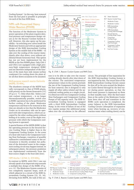
NPP Atucha 1 (CNA 1), 319 MW el<br />
In contrast to MZFR, with CNA 1 one can<br />
already speak <strong>of</strong> an important step towards<br />
a multiple-line design <strong>of</strong> the RHRC (F i g -<br />
u r e 8 ). The Moderator System consists <strong>of</strong><br />
two completely separate loops, each <strong>of</strong><br />
which adjacent to a circuit <strong>of</strong> the RHR Intermediate<br />
Cooling System [12, 13, 14].<br />
Deviating from MZFR, the task <strong>of</strong> this system<br />
is to be able to take over the reactor<br />
cooling already shortly after shut down <strong>of</strong><br />
the reactor. The associated temperature<br />
<strong>and</strong> pressure values in the system preclude<br />
the use <strong>of</strong> the Component Cooling System<br />
<strong>for</strong> heat removal; this is designed to only<br />
supply all other safety-related <strong>and</strong> the operational<br />
cooling points as a single circuit.<br />
It is fitted out with two Component Cooling<br />
<strong>Heat</strong> Exchangers <strong>and</strong> Component Cooling<br />
Pumps <strong>of</strong> full capacity each. The RHR Intermediate<br />
Cooling System is equipped<br />
with a third RHR Intermediate Cooling<br />
Pump. In the event <strong>of</strong> failure <strong>of</strong> one <strong>of</strong> the<br />
two regular pumps this additional pump<br />
takes over the circulation in the affected<br />
SG<br />
2 1 1 2<br />
Feed Water<br />
System<br />
3 3 3<br />
4 4<br />
5<br />
RCP<br />
6<br />
Main Steam System<br />
Reactor Coolant System<br />
Moderator System<br />
RHR Intermediate<br />
Cooling System<br />
Component Cooling<br />
System<br />
Secured Service<br />
Cooling Water System<br />
8<br />
Fig. 8. CNA 1, Reactor Coolant System <strong>and</strong> RHR Chain.<br />
7<br />
9<br />
SG Steam Generator<br />
RCP Reactor Coolant Pump<br />
1 Moderator Pumps<br />
2 Moderator Coolers<br />
3 RHR Intermediate<br />
Cooling Pumps<br />
4 RHR Intermediate<br />
Cooling <strong>Heat</strong> Exchanger<br />
5 Secured Service<br />
Cooling Water Pumps<br />
6 Component<br />
Cooling Pumps<br />
7 Component Cooling<br />
<strong>Heat</strong> Exchanger<br />
8 Component Cooling<br />
Water Consumers<br />
9 Fuel Pool Coolers<br />
circuit. The principle <strong>of</strong> line separation <strong>for</strong><br />
the RHR Intermediate Cooling System is<br />
not impaired by this. The return lines <strong>of</strong> the<br />
RHR Intermediate Cooling Circuits cannot<br />
be shut <strong>of</strong>f to the area around the Moderator<br />
Cooler flowed through by the feed water<br />
during power operation, so that the<br />
feed water pressure is impressed on them<br />
in their st<strong>and</strong>by state. After the feed water<br />
lines at the outlet <strong>of</strong> the Moderator Cooler<br />
have been shut <strong>of</strong>f <strong>and</strong> transition to the<br />
RHRC cycle operation is completed, the<br />
water balance in the RHR Intermediate<br />
Cooling Circuits (absorption <strong>of</strong> expansion<br />
water when heating up, recovery <strong>of</strong> contraction<br />
water when cooling down) can be<br />
SG Reactor SG<br />
RCP<br />
Main Steam System<br />
Reactor Coolant<br />
System<br />
RCP Reactor Coolant Pump<br />
SG SteamGenerator<br />
1 Moderator Pumps<br />
2 Moderator Coolers<br />
3<br />
4<br />
5<br />
6<br />
Moderator System Safety Component Cooling System Secured Service<br />
Cooling Water<br />
System<br />
RHR Intermediate<br />
Cooling System<br />
Operation Component<br />
Cooling System<br />
RHR Intermediate Cooling Pumps<br />
RHR Intermediate Cooling <strong>Heat</strong> Exchangers<br />
Secured Service Cooling Water Pumps<br />
Component Cooling Pumps<br />
Fig. 9. CNA 2, Reactor Coolant System <strong>and</strong> RHR Chain.<br />
RCP<br />
7 Component Cooling <strong>Heat</strong> Exchangers<br />
8 Component Cooling Water Consumers<br />
9 Fuel Pool Coolers<br />
10 Secured Intermediate Coolers<br />
53


