

VGB POWERTECH 5 (2021) - International Journal for Generation and Storage of Electricity and Heat
VGB PowerTech - International Journal for Generation and Storage of Electricity and Heat. Issue 5 (2021). Technical Journal of the VGB PowerTech Association. Energy is us! Nuclear power. Nuclear power plants - operation and operation experiences
VGB PowerTech - International Journal for Generation and Storage of Electricity and Heat. Issue 5 (2021).
Technical Journal of the VGB PowerTech Association. Energy is us!
Nuclear power. Nuclear power plants - operation and operation experiences

Create successful ePaper yourself
Turn your PDF publications into a flip-book with our unique Google optimized e-Paper software.
Safety-related residual heat removal chains <strong>for</strong> pressure water reactors <strong>VGB</strong> PowerTech 5 l <strong>2021</strong><br />
a few safety-relevant additions – became<br />
the st<strong>and</strong>ard <strong>and</strong> has since been used <strong>for</strong> all<br />
following PLWR plants [5, 6]. The number<br />
<strong>of</strong> RHR lines usually, but not necessarily,<br />
corresponds to the number <strong>of</strong> reactor cooling<br />
loops. For this size <strong>of</strong> units (<strong>and</strong> also <strong>for</strong><br />
the EPR concept (≥ 1,600 MWel) four<br />
Steam Generators <strong>and</strong> thus four reactor<br />
cooling loops are required <strong>for</strong> heat transfer<br />
to the water/steam cycle in power operation.<br />
Accordingly, the RHRC also consists <strong>of</strong><br />
four independent RHR lines with a heat<br />
transfer capacity <strong>of</strong> 50 % each, based on the<br />
design case. (Note: Even <strong>for</strong> plants with<br />
only three reactor cooling loops, this “one<br />
to one” assignment <strong>of</strong> loop <strong>and</strong> line number<br />
can be obtained without violating the safety<br />
philosophy (repair <strong>and</strong> simultaneously<br />
single-failure) when the heat transfer capacity<br />
<strong>of</strong> each line is increased to 100 %.) In<br />
F i g u r e 5 , the two inner Component Cooling<br />
Circuits are designed <strong>for</strong> the alternating<br />
supply <strong>of</strong> operational component points.<br />
For this purpose, in addition to the regular<br />
Component Cooling Pump, a second pump<br />
is connected in parallel, operated in case <strong>of</strong><br />
a very high cooling water dem<strong>and</strong>.<br />
NPPs <strong>of</strong> DWR 1300 MW class<br />
The increasing safety-related requirements,<br />
set down e.g. in the “RSK Guidelines<br />
<strong>for</strong> Pressurized Water Reactors” [7]<br />
<strong>and</strong> in “Safety Regulations <strong>of</strong> the KTA”<br />
[8, 9], in particular<br />
––<br />
elevated awareness <strong>of</strong> the fuel pool inventory<br />
as a source <strong>of</strong> activity, <strong>and</strong><br />
––<br />
the inclusion <strong>of</strong> “civilization-related external<br />
impacts” (aircraft crash, explosion<br />
pressure waves, third part influences) as<br />
cases to be managed,<br />
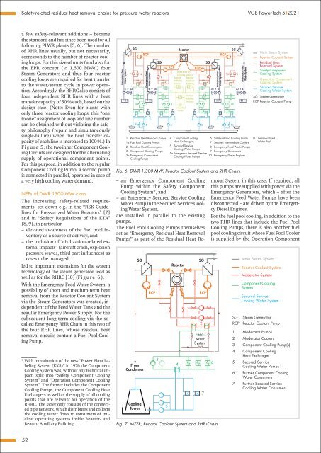
led to important extensions <strong>for</strong> the system<br />
technology <strong>of</strong> the steam generator feed as<br />
well as <strong>for</strong> the RHRC [10] (F i g u r e 6 ).<br />
With the Emergency Feed Water System, a<br />
possibility <strong>of</strong> short <strong>and</strong> medium-term heat<br />
removal from the Reactor Coolant System<br />
via the Steam Generators was created, independent<br />
<strong>of</strong> the Feed Water Tank <strong>and</strong> the<br />
regular Emergency Power Supply. For the<br />
subsequent long-term cooling via the socalled<br />
Emergency RHR Chain in this two <strong>of</strong><br />
the four RHR lines, whose residual heat<br />
removal circuits contain a Fuel Pool Cooling<br />
Pump,<br />
* With introduction <strong>of</strong> the new “Power Plant Labeling<br />
System (KKS)” in 1976 the Component<br />
Cooling System was, without any technical impact,<br />
split into “Safety Component Cooling<br />
System” <strong>and</strong> “Operation Component Cooling<br />
System”. The <strong>for</strong>mer includes the Component<br />
Cooling Pumps, the Component Cooling <strong>Heat</strong><br />
Exchangers as well as the supply <strong>of</strong> all cooling<br />
points that are relevant <strong>for</strong> operation <strong>of</strong> the<br />
RHRC. The latter only consists <strong>of</strong> the connected<br />
pipe network, which distributes <strong>and</strong> collects<br />
the cooling water flows to consumers <strong>of</strong> nuclear<br />
operating systems inside Reactor- <strong>and</strong><br />
Reactor Auxiliary Building.<br />
SG<br />
RCP<br />
SG<br />
1 Residual <strong>Heat</strong> Removal Pumps<br />
1a Fuel Pool Cooling Pumps<br />
2 Residual <strong>Heat</strong> Exchangers<br />
3 Component Cooling Pumps<br />
3a Emergency Component<br />
Cooling Pumps<br />
RCP<br />
Reactor<br />
RCP<br />
4 Component Cooling<br />
<strong>Heat</strong> Exchangers<br />
5 Secured Service<br />
Cooling Water Pumps<br />
5a Emergency Secured Service<br />
Cooling Water Pumps<br />
SG<br />
RCP<br />
SG<br />
6 Safety-related Cooling Points<br />
7 Secured Intermediate Coolers<br />
8 Emergency Feed Water Pumps<br />
9 Emergency Generators<br />
10 Emergency Diesel Engines<br />
Fig. 6. DWR 1,300 MW, Reactor Coolant System <strong>and</strong> RHR Chain.<br />
SG<br />
From<br />
Condenser<br />
Cooling<br />
Tower<br />
RCP<br />
3<br />
5<br />
Reactor<br />
SG<br />
RCP<br />
Feedwater<br />
System<br />
Fig. 7. MZFR, Reactor Coolant System <strong>and</strong> RHR Chain.<br />
4<br />
1<br />
2<br />
7<br />
Main Steam System<br />
Reactor Coolant System<br />
Residual <strong>Heat</strong><br />
Removal System<br />
Safety Component<br />
Cooling System<br />
Operation Component<br />
Cooling System<br />
Secured Service<br />
Cooling Water System<br />
SG Steam Generator<br />
RCP Reactor Coolant Pump<br />
11 Demineralized<br />
Water Pool<br />
––<br />
an Emergency Component Cooling<br />
Pump within the Safety Component<br />
Cooling System*, <strong>and</strong><br />
––<br />
an Emergency Secured Service Cooling<br />
Water Pump in the Secured Service Cooling<br />
Water System.<br />
are installed in parallel to the existing<br />
pumps.<br />
The Fuel Pool Cooling Pumps themselves<br />
act as “Emergency Residual <strong>Heat</strong> Removal<br />
Pumps” as part <strong>of</strong> the Residual <strong>Heat</strong> Removal<br />
System in this case. If required, all<br />
this pumps are supplied with power via the<br />
Emergency Generators, which – after the<br />
Emergency Feed Water Pumps have been<br />
disconnected – are driven by the Emergency<br />
Diesel Engines.<br />
For the fuel pool cooling, in addition to the<br />
two RHR lines that include the Fuel Pool<br />
Cooling Pumps, there is also another fuel<br />
pool cooling circuit whose Fuel Pool Cooler<br />
is supplied by the Operation Component<br />
6<br />
SG<br />
RCP<br />
1<br />
2<br />
3<br />
4<br />
5<br />
6<br />
7<br />
Main Steam System<br />
Reactor Coolant System<br />
Moderator System<br />
Component Cooling<br />
System<br />
Secured Service<br />
Cooling Water System<br />
Steam Generator<br />
Reactor Coolant Pump<br />
Moderator Pumps<br />
Moderator Coolers<br />
Component Cooling Pump(s)<br />
Component Cooling<br />
<strong>Heat</strong> Exchanger<br />
Secured Service<br />
Cooling Water Pumps<br />
Further Component Cooling<br />
Water Consumers<br />
Further Secured Service<br />
Cooling Water Consumers<br />
52


