

VGB POWERTECH 5 (2021) - International Journal for Generation and Storage of Electricity and Heat
VGB PowerTech - International Journal for Generation and Storage of Electricity and Heat. Issue 5 (2021). Technical Journal of the VGB PowerTech Association. Energy is us! Nuclear power. Nuclear power plants - operation and operation experiences
VGB PowerTech - International Journal for Generation and Storage of Electricity and Heat. Issue 5 (2021).
Technical Journal of the VGB PowerTech Association. Energy is us!
Nuclear power. Nuclear power plants - operation and operation experiences

Create successful ePaper yourself
Turn your PDF publications into a flip-book with our unique Google optimized e-Paper software.
Safety-related residual heat removal chains <strong>for</strong> pressure water reactors <strong>VGB</strong> PowerTech 5 l <strong>2021</strong><br />
carried out via expansion tanks as well as<br />
discharges to the feed water tank on the one<br />
h<strong>and</strong>, <strong>and</strong> feed from the feed water tank or<br />
the deionized water tank by means <strong>of</strong> system-associated<br />
pumps on the other h<strong>and</strong>.<br />
A line assignment has not yet been made <strong>for</strong><br />
the outer RHRC link, the Secured Service<br />
Cooling Water System. Three parallel Secured<br />
Service Cooling Water Pumps can feed<br />
a manifold, from which all intercoolers as<br />
well as the Fuel Pool Coolers are supplied.<br />
NPP Atucha 2 (CNA 2), 692 MW el<br />
A clear line separation concept has been<br />
implemented at CNA 2. Although the plant<br />
only has two reactor cooling circuits, the<br />
Moderator System <strong>and</strong> the entire RHRC are<br />
constructed with four lines, each <strong>of</strong> them<br />
having a capacity <strong>of</strong> 50 % <strong>of</strong> the total power<br />
to be removed in the design case. Thus the<br />
“repair + single-failure” criterion <strong>for</strong> accidents<br />
is fulfilled. Not only the RHR Intermediate<br />
Cooling System, but also the Safety<br />
Component Cooling System here consists<br />
<strong>of</strong> four circuits, which supply the<br />
respective associated consumers – i.e.<br />
pumps <strong>and</strong> their motors – with cooling water.<br />
The circuits <strong>of</strong> the two outer redundancies<br />
in F i g u r e 9 can also be optionally<br />
switched on to cooling points <strong>of</strong> the fuel<br />
assembly transport devices (not shown in<br />
F i g u r e 9 ). One circuit <strong>of</strong> the two inner<br />
redundancies serves not only its safety-relevant<br />
consumers, but also the Operation<br />
Component Cooling System, the other one<br />
st<strong>and</strong>s by <strong>for</strong> that. The design <strong>of</strong> the RHR<br />
Intermediate Cooling System enables – if<br />
necessary – a takeover <strong>of</strong> heat transfer<br />
from the reactor cooling system after shutdown<br />
<strong>of</strong> the plant without the aid <strong>of</strong> steam<br />
generator feed. To achieve the maximum<br />
possible heat removal capacity, the bypasses<br />
inside the RHR Intermediate Cooling<br />
Circuit around Moderator Cooler <strong>and</strong> RHR<br />
Intermediate Cooling <strong>Heat</strong> Exchanger<br />
must be closed. If it is necessary <strong>for</strong> the<br />
RHRC to keep the reactor cooling system in<br />
a desired temperature state or to cool it<br />
down according to a specified shutdown<br />
gradient, this is done by opening/closing<br />
the bypass around the Moderator Cooler<br />
(without intermediate positions) <strong>and</strong> by<br />
controlling the flow rate through the primary<br />
side <strong>of</strong> the RHR Intermediate Cooling<br />
<strong>Heat</strong> Exchanger on the one h<strong>and</strong> <strong>and</strong> the<br />
bypass around the cooler on the other<br />
(Shutdown control).<br />
An important further development compared<br />
to CNA 1 is the h<strong>and</strong>ling <strong>of</strong> the water<br />
balance in the RHR Intermediate Cooling<br />
Circuits. Facilities <strong>for</strong> absorbing expansion<br />
water <strong>and</strong> re-feeding it when the circuit<br />
cools down as well as replacing operational<br />
medium losses in the first period after an<br />
accident occurs (in the event <strong>of</strong> failure <strong>of</strong><br />
operational demineralized water supply)<br />
are set up <strong>for</strong> each circuit self-sufficient<br />
<strong>and</strong> spatially separated from each other in<br />
the Reactor Building Annulus.<br />
Each <strong>of</strong> the four subsystems <strong>of</strong> the Secured<br />
Service Cooling Water System with one Secured<br />
Service Cooling Water Pump each,<br />
supplies all <strong>of</strong> the assigned heat exchangers<br />
in parallel, that are:<br />
––<br />
One RHR Intermediate Cooling <strong>Heat</strong> Exchanger,<br />
––<br />
One Component Cooling <strong>Heat</strong> Exchanger,<br />
––<br />
One Secured Intermediate Cooler,<br />
––<br />
This heat exchanger removes the heat<br />
loss from the line-assigned Emergency<br />
Diesel Engine <strong>and</strong> the Secured Chilled<br />
Water System, which is absorbed in the<br />
so-called Secured Closed Cooling Water<br />
System.<br />
––<br />
One Fuel Pool Cooler (Really only a total<br />
<strong>of</strong> two coolers, each <strong>of</strong> which con-<br />
SG<br />
SG<br />
RCP<br />
RHR Intermediate<br />
Cooling System<br />
Main Steam System<br />
Reactor Coolant System<br />
RCP<br />
Main Steam System<br />
Reactor Coolant System<br />
SG<br />
RCP<br />
Residual <strong>Heat</strong> Removal System<br />
Safety Component Cooling System<br />
Moderator System<br />
RHR Intermediate<br />
Cooling System<br />
Reactor<br />
nected to two Secured Service Cooling-<br />
Water Pumps <strong>for</strong> alternating supply)<br />
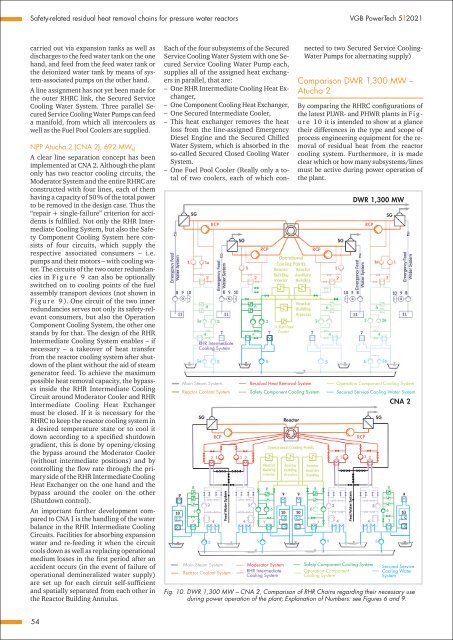
Comparison DWR 1,300 MW –<br />
Atucha 2<br />
By comparing the RHRC configurations <strong>of</strong><br />
the latest PLWR- <strong>and</strong> PHWR plants in F i g -<br />
u r e 10 it is intended to show at a glance<br />
their differences in the type <strong>and</strong> scope <strong>of</strong><br />
process engineering equipment <strong>for</strong> the removal<br />
<strong>of</strong> residual heat from the reactor<br />
cooling system. Furthermore, it is made<br />
clear which or how many subsystems/lines<br />
must be active during power operation <strong>of</strong><br />
the plant.<br />
SG<br />
RCP<br />
Safety Component Cooling System<br />
Operation Component<br />
Cooling System<br />
DWR 1,300 MW<br />
RCP<br />
Operation Component Cooling System<br />
Secured Service Cooling Water System<br />
SG<br />
SG<br />
CNA 2<br />
Secured Service<br />
Cooling Water<br />
System<br />
Fig. 10. DWR 1,300 MW – CNA 2, Comparison <strong>of</strong> RHR Chains regarding their necessary use<br />
during power operation <strong>of</strong> the plant; Explanation <strong>of</strong> Numbers: see Figures 6 <strong>and</strong> 9.<br />
RCP<br />
54


