FACA AAC AC-SIMILE LE - Nilfisk PARTS - Nilfisk-Advance
FACA AAC AC-SIMILE LE - Nilfisk PARTS - Nilfisk-Advance
FACA AAC AC-SIMILE LE - Nilfisk PARTS - Nilfisk-Advance

Erfolgreiche ePaper selbst erstellen
Machen Sie aus Ihren PDF Publikationen ein blätterbares Flipbook mit unserer einzigartigen Google optimierten e-Paper Software.
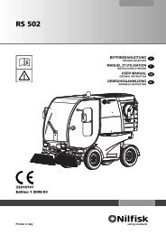
USER MANUAL<br />
UNP<strong>AC</strong>KING/DELIVERY<br />
The machine is delivered already assembled and<br />
ready-to-use, unpacking/installation procedures are not<br />
necessary.<br />
Please check that the following items have been supplied with<br />
the machine:<br />
– Technical documents:<br />
– Sweeper User Manual<br />
– Diesel Engine Manual<br />
– Sweeper Spare Parts List<br />
M<strong>AC</strong>HINE DESCRIPTION<br />
OPERATION CAPABILITIES<br />
This sweeper has been designed and built to be used by a<br />
qualified operator to clean (by sweeping and suctioning)<br />
roads, smooth and solid floors, in civil and industrial<br />
environments, and to collect dust and light debris under safe<br />
operation conditions.<br />
CONVENTIONS<br />
Forward, backward, front, rear, left or right are intended with<br />
reference to the operator’s position, while on the driver’s seat<br />
(17, Fig. E).<br />
DESCRIPTION<br />
Description of the control area<br />
(See Fig. D)<br />
1. Meter and control panel<br />
2. Indicators and warning lights<br />
3. Optional indicator light<br />
4. Optional indicator light<br />
5. Engine coolant temperature<br />
6. High beam indicator light<br />
7. Running light indicator light<br />
8. Charged battery indicator light (a buzzer activates<br />
together with the indicator light)<br />
9. Parking brake warning light<br />
10. Glow plug pre-heating warning light<br />
11. Hour counter/revolution counter display:<br />
– It displays the hours, when the ignition key (17, Fig.<br />
D) is turned on the first position, before running the<br />
engine<br />
– It displays the engine speed, when the engine is<br />
running and the charged battery warning light is off<br />
12. Charged battery indicator light (a buzzer activates<br />
together with the indicator light)<br />
13. Optional indicator light<br />
14. Engine coolant high temperature warning light (a buzzer<br />
activates together with the warning light)<br />
15. Charged battery indicator light (a buzzer activates<br />
together with the indicator light)<br />
16. Turn signal indicator light<br />
17. Ignition switch<br />
18. Climate control system switch (*)<br />
19. Dust control system switch<br />
20. Windscreen wiper/washer switch<br />
21. Cab air flow switch (two speed)<br />
22. Hazard warning light switch<br />
23. Dust control system water tank warning light (red)<br />
24. Fuse box B (see the Electrical Fuses paragraph)<br />
25. Fuse box A (see the Electrical Fuses paragraph)<br />
26. Lifted hopper warning light (red)<br />
27. Warning buzzer (it activates together with the warning<br />
lights 8, 12, 14, 15)<br />
28. Hopper lid opening/closing switch<br />
29. Sun visor<br />
(See Fig. E)<br />
1. Combination switch, having the following functions:<br />
– Headlights off, with mark (1b) at the symbol O<br />
– Running lights on, with mark (1b) at the<br />
symbol<br />
– Low beam on, with mark (1b) at the<br />
symbol<br />
– High beam on, with mark (1b) at the<br />
symbol and lowered lever (1a)<br />
– High beam temporary on, lifting the lever (1a)<br />
– Right turn signal on, bringing the lever (1a) forward<br />
– Left turn signal on, bringing the lever (1a) backward<br />
– Horn activation, pushing the lever (1a) in the<br />
direction shown by the arrow (1c)<br />
2. Steering wheel<br />
3. Windscreen wiper motor<br />
4. Drive pedal<br />
– to be pressed on the front side to move forward<br />
– to be pressed on the rear side to move backward<br />
5. Brake pedal<br />
6. Steering wheel adjusting lever<br />
7. Parking brake lever<br />
8. Suction inlet dust control system nozzle tap<br />
9. Broom dust control system nozzle tap<br />
10. Hopper lifting/lowering lever<br />
11. Driver's seat safety belt (*)<br />
12. Suction inlet and broom lifting/lowering lever<br />
13. Skirt opening/closing switch<br />
14. Suction activation lever<br />
15. Cab heater control knob<br />
16. Diesel engine throttle lever<br />
17. Driver's seat<br />
18. Battery<br />
19. Cab left panel<br />
20. Cab right panel<br />
21. Serial number plate/technical data/EC certification<br />
22. Driver's seat forward/backward adjustment lever<br />
23. Hopper lifting/lowering lever safety flange<br />
24. Suction inlet and broom lifting/lowering lever safety<br />
flange<br />
25. High-pressure water gun<br />
26. Document holder<br />
27. Windscreen wiper fluid tank<br />
28. Broom speed adjuster (*)<br />
29. Ashtray<br />
30. High-pressure water gun sprinkler nozzle<br />
31. Cigarette lighter<br />
32. Can holder<br />
6 33014085(3)2006-06 A