- Page 1 and 2:
dine Series Emission Standards and
- Page 3 and 4: TABLE OF CONTENTS ................
- Page 5 and 6: D.2 THERMAL INCINERATOR VOC EMISSIO
- Page 7 and 8: LIST OF TABLES End Uses of Polyprop
- Page 9 and 10: Typical Inci nerator Parameters for
- Page 11: LIST OF FIGURES Simplified Process
- Page 15 and 16: 2.1 INTRODUCTION 2.0 PROCESS AND PO
- Page 17 and 18: Polypropylene resins are supplied i
- Page 19 and 20: Table 2-2. POLYPROPYLENE (PP) PLANT
- Page 21 and 22: Fxlrus loll l'el lciiz ltlq Methano
- Page 23 and 24: Tab1e 2-3. CHARACTER1 STICS OF VENT
- Page 25 and 26: in addition to C3 and process dilue
- Page 27 and 28: used in maki fig shopping bags. For
- Page 29 and 30: I 2 CTC E%% PCS A wrcc 2 C W P U iZ
- Page 31 and 32: Table '2-6. CHARACTERISTICS OF VENT
- Page 33 and 34: A1 though polymers with molecular w
- Page 35 and 36: A - . STYREL +VACUUH SYSTEM (8) (9)
- Page 37 and 38: Tab1e 2-8. CHARACTERISTICS OF VENT
- Page 41 and 42: 3.0 EMISSION CONTROL TECHNIQUES Vol
- Page 43 and 44: that they require for complete comb
- Page 45 and 46: PILOT AND CENTER mAlri JET ELNATION
- Page 47 and 48: Ground flares are usually enclosed
- Page 49 and 50: flare was operated with from 130 t
- Page 51 and 52: w Table 3-1 . FLARE EMISSIONS STUDI
- Page 53: has become less common during the p
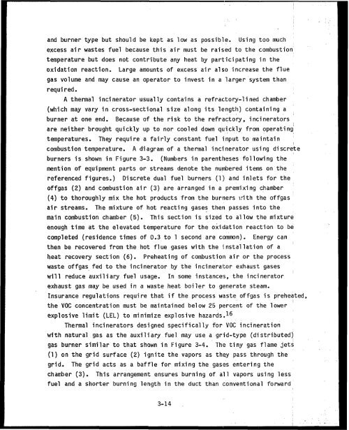
- Page 57 and 58: chamber temperatures ranging from 7
- Page 59 and 60: = alti-
- Page 61 and 62: control can be used. Any breakdown
- Page 63 and 64: and, in some cases, reused in the p
- Page 65 and 66: are immiscible with the coolant. Th
- Page 67 and 68: 3.2 .I .1 Condenser Control Efficie
- Page 69 and 70: VOC -*, VENT TO VcntS~ AmOSPnERE Fi
- Page 71 and 72: ABSORBlHG UQUlD WITH VOC OUT To Dis
- Page 73 and 74: REFERENCES FOR CHAPTER 3 Lee, K.C.,
- Page 75 and 76: Reference 24, p. 34. Key, J . A. Or
- Page 77 and 78: 4.1 INTRODUCTION 4.0 ENVIRONME NTAL
- Page 79 and 80: Table 4-1. UNCONTROLLED EMISSION RA
- Page 81 and 82: C Table 4-3. UNCONTROLLED EMISSION
- Page 83 and 84: the results and an analysis of cost
- Page 85 and 86: Tab1e 4-4. MODEL PLANT ENVIRONMENTA
- Page 87 and 88: Tab1e 4-5. ADDITIONAL ENERGY REQUIR
- Page 89 and 90: -- Table 4-7. ADDITIONAL ENERGY REQ
- Page 91 and 92: 5.0 CONTROL COST ANALYSIS OF RACT T
- Page 93 and 94: m I W 1. Simple. continuous uanuall
- Page 95 and 96: Tab1e 5-2, INSTALLATION COST FACTOR
- Page 97 and 98: FOOTNOTES FOR Tab1 e 5-3 a Incl ude
- Page 99 and 100: In order to prevent an explosion ha
- Page 101 and 102: analysis of the Distil 1 ation NSPS
- Page 103 and 104: Install ed piping and ducting costs
- Page 105 and 106:
estimated by the same procedure as
- Page 107 and 108:
.ble 5-4. POLYPROPYLENE MODEL PLANT
- Page 109 and 110:
Table 5-6. POLYSTYRENE MODEL PLANT
- Page 111 and 112:
emitters, while other dryers, e.g.,
- Page 113 and 114:
Table 5-8. COST ANALYSIS FOR POLYPR
- Page 115 and 116:
other dryers may have higher or low
- Page 117 and 118:
Table 5-11. COST ANALYSIS FOR HIGH
- Page 119 and 120:
Table 5-12. COST ANALYSIS FOR POLYS
- Page 122 and 123:
Polymer Table 5-15. COST EFFECTIVEN
- Page 124 and 125:
effectiveness of polystyrene contro
- Page 126 and 127:
EEA. Distil lation NSPS Pi peline C
- Page 129 and 130:
APPENDIX A LIST OF COMFIENJERS
- Page 131 and 132:
APPENDIX B COMMENTS OW MAY 1982 DRA
- Page 133 and 134:
Mr. J. R. Famet Page 2 EPA June 16,
- Page 135 and 136:
October 19, 1981 Attachment to June
- Page 137 and 138:
Be The mocial plant does nst incEud
- Page 139 and 140:
1000 BRAZOS, SUITE 200, AUSTIN, TEX
- Page 141 and 142:
our previous comments the TCC quest
- Page 143 and 144:
. . . . " . . 5. Emission Reduction
- Page 145 and 146:
REFERENCES Texas Chemical Council t
- Page 147 and 148:
' Y !. Jack R. Faner o The A~ency h
- Page 149 and 150:
NATION& AIR POLLUTION CONTROL Y COM
- Page 151:
" DEFINITION OF INCINERATION AS MCT
- Page 154 and 155:
-5- IN SUWRYj THE AGENCY, BY RELYIN
- Page 156 and 157:
STRUMS WITH RELATIVELY STABLE FLOW
- Page 158 and 159:
1 I CoHPlTIONS OF 10 TIMES NORMAL S
- Page 160 and 161:
I 1 I - gU - I I n G PROPO.SED INCI
- Page 162:
The use of data from the CTG for ai
- Page 166:
Mr. Jack R. Farmer, Chief July 19,
- Page 169 and 170:
APPENDIX C MAJOR ISSUES AND RESPONS
- Page 171 and 172:
generally for large volume, variabl
- Page 173 and 174:
control devices, such as thermal an
- Page 175 and 176:
modification or rep1 acement, based
- Page 177 and 178:
epresent excellent agreement for su
- Page 179 and 180:
Response: The following responses a
- Page 181:
processes (e.g ., polypropylene and
- Page 184 and 185:
I I I I The purpose of this appendi
- Page 187 and 188:
Data collection continued for each
- Page 189 and 190:
Test . Number ~104Velocity (scfm) (
- Page 191 and 192:
found for tests of incinerators at
- Page 194 and 195:
7' Tab1e 0-4. TYPICAL INCINERATOR P
- Page 196 and 197:
I I I I I l l I averages for the mo
- Page 198 and 199:
Table D-5. ARC0 POLYMERS INCINERATO
- Page 200 and 201:
Thempies Spaced Evenly Across the T
- Page 202 and 203:
probe for the temperature while a w
- Page 204 and 205:
The total installed capital cost of
- Page 206 and 207:
3. Test Results - VOC destruction e
- Page 208 and 209:
Figure D-4. Petro-Tex 0x0 unit inci
- Page 210 and 211:
air to reduce the air flow through
- Page 213 and 214:
HEAT EXCHANGE1 NOTE: From Exchanger
- Page 215 and 216:
' organic carbon. chromatography. T
- Page 217 and 218:
D.3 VAPOR RECOVERY SYSTEM VOC EMISS
- Page 219:
However, the calculations assume pe
- Page 222 and 223:
The 20 pprn level was judged to be
- Page 224 and 225:
REFERENCES FOR APPENDIX D McDaniel,
- Page 227 and 228:
APPENDIX E: DETAILED DESIGN AND COS
- Page 229 and 230:
characteristics: volumetric flow ra
- Page 231 and 232:
Footnotes for Table E-1 astandad co
- Page 233 and 234:
sources to the flare header were as
- Page 235:
Flare Tip Diameter (in.) Figure E-1
- Page 238 and 239:
Table E-3. CAPITAL AND ANNUAL OPERA
- Page 240 and 241:
Footnotes for Table E-3 aFluidic se
- Page 242 and 243:
Tab1e E-4. WtORKSHEET FOR CALCULATI
- Page 244 and 245:
excess air for oxygen in the waste
- Page 246 and 247:
Table E-6. PROCEDURE TO DESIGN THER
- Page 248:
I I a plant had a use for it, heat
- Page 252 and 253:
Footnotes for Table E-7 Wpdated usi
- Page 255 and 256:
Table E-8. OPERATING PARAMETERS AND
- Page 257:
TABLE E-9. GAS PARAMETERS USED FOR
- Page 260 and 261:
~ 1 1 I I l 1 I I represent June 19
- Page 262 and 263:
Tabl e -11 CAPITAL AND . IERATIONG
- Page 264 and 265:
$0.335/scfm for units with no heat
- Page 266 and 267:
Table E-12. PROCEDURE TO CALCULATE
- Page 268 and 269:
Footnotes for Table E-12 (Concluded
- Page 270 and 271:
i m- Table E-13. PROCEDURE TO CALCU
- Page 272 and 273:
I - I - 1 A nnnrrn~~nrc rn rnl PIII
- Page 274 and 275:
Table E-15. CAPITAL AND ANNUAL OPER
- Page 276 and 277:
aUpdated using Chemical ~ I nneiri
- Page 278 and 279:
Condenser ~y2 ! ;tern Area (ftL) Fi
- Page 280 and 281:
ased on an equation in the Chemical
- Page 282 and 283:
m Equi p ent Type Check Valves Gate
- Page 284 and 285:
- 1/8 - - Table E-20. INSTALLED DUC
- Page 286 and 287:
Reference 12, p. 6-3 and 6-4. Refer
- Page 289 and 290:
APPENDIX F CALCULATION OF UNCONTROL
- Page 291 and 292:
Table F-1 . INITIAL EMISSION CHARAC
- Page 293 and 294:
Table F12. SUMMARY OF ANNUAL COSTS,
- Page 295:
= the difference between the operat
- Page 298 and 299:
I 8 - a F.Z. 1 Sty rene-i n-Steam m
- Page 300 and 301:
(9 CE = AC - (0.9 ~ CDnA ~ x eRC) d
- Page 302 and 303:
Substituting the values from Table
- Page 304 and 305:
Table 7. EXPONENTS USED FOR CONDENS
- Page 306 and 307:
Within Line Table F-8. STYRENE'-IN-


