Levelflex M FMP40 - Process Centre Of Excellence.
Levelflex M FMP40 - Process Centre Of Excellence.
Levelflex M FMP40 - Process Centre Of Excellence.

You also want an ePaper? Increase the reach of your titles
YUMPU automatically turns print PDFs into web optimized ePapers that Google loves.
<strong>Levelflex</strong> M <strong>FMP40</strong> with HART/4...20 mA Mounting<br />
• It is also possible to mount the probe externally on the tank wall for measuring in Aqueous<br />
solutions. Measurement then takes place through the tank wall without contacting the medium.<br />
If people are in the vicinity of the probe mounting location, a plastic half pipe with a diameter of<br />
approx. 200 mm, or some other protective unit, must be affixed externally to the probe to prevent<br />
any influences on the measurement.<br />
• There must not be any metallic reinforcement rings secured to the tank.<br />
• The wall thickness should be at Fibre-Glass Reinforced Plastic/PP < 15 mm.<br />
• There must be no open space between the tank wall and the probe.<br />
• If measuring externally, an automatic probe length determination and a two point linearisation<br />
must be performed in order to compensate for the time-of-flight change caused by the plastic wall.<br />
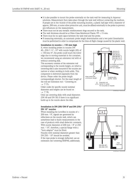
Installation in nozzles > 150 mm high<br />
If, when installing probes in nozzles DN<br />
40...250/1 ½"...10" with nozzle height (HS) of<br />
> 150 mm/6", the probe could touch the lower<br />
edge due to moving materials in the container,<br />
we recommend using an extension rod with or<br />
without centering disk.<br />
This accessory consists of the extension rod<br />
corresponding to the nozzle height, on which a<br />
centering disk is also mounted if the nozzles are<br />
narrow or when working in bulk solids. This<br />
component is delivered separately from the<br />
device. Please order the probe length<br />
correspondingly shorter. For the exact length of<br />
the rod see Extension rod / Centering on<br />
→ ä 75.<br />
Order codes for specific nozzle nominal<br />
diameters and heights can be found on<br />
→ ä 78.<br />
Only use centering disks with small diameters<br />
(DN 40 and DN 50) if there is no significant<br />
build-up in the nozzle above the disk.<br />
Installation in DN 200/DN 8"and DN 250/<br />
DN 10" nozzles<br />
When installing the <strong>Levelflex</strong> in nozzles of ><br />
200 mm / 8", signals are generated by<br />
reflections on the nozzle wall, which can<br />
sometimes lead to faulty measurements in the<br />
case of products with small dielectric constants.<br />
With nozzle diameters of 200 mm / 8" or 250<br />
mm / 10", therefore, a special flange with a<br />
“horn adaptor” must be fitted.<br />
Nozzles with nominal diameters greater than<br />
DN 250 / 10" should be avoided.<br />
If the rope probe is strongly deflected: use an<br />
extension rod/centering HMP40, additionaly.<br />
L00-FMP4xxxx-17-00-00-en-025<br />
Endress + Hauser 31<br />
nozzle<br />
height<br />
Keep metal tube<br />
at minimum length!<br />
#<br />
DN 50 (2")<br />
DN 80 (3")<br />
DN 150 (6")<br />
DN 200 (8")<br />
DN 250 (10")<br />
For DN200 and DN250<br />
in combination<br />
with horn adapter<br />
centering disk<br />
at PPS - GF40<br />
Extension rod<br />
Not for ¾" probe.<br />
For rod probe on request.<br />
DN 200 (8")<br />
DN 250 (10")<br />
204 mm<br />
max.<br />
~150 mm<br />
L00-FMP4xxxx-17-00-00-de-026
![[MI 019-120] I/A Series Mass Flowtubes Models CFS20 ... - Invensys](https://img.yumpu.com/48832334/1/190x245/mi-019-120-i-a-series-mass-flowtubes-models-cfs20-invensys.jpg?quality=85)