
Create successful ePaper yourself
Turn your PDF publications into a flip-book with our unique Google optimized e-Paper software.
636<br />
XXI. Td~nlcnt houndnry layers at zoro promure gredicnt a. The smooth flat platc '<br />
R = I/, 1/v (Urn - frcc-strca~n vclocity; 1 - length of plate) are so large t1hat they<br />
cannot bc strbjcctcd to mcasurcment in a laboratory. Moreover, even at motlerate<br />
Itcynol(1s numhcrs it is murh morc difficult to carry out mcasuremcnts in the<br />
bounclnry Iaycr on a plate than in that inside a pipe. It is, therefore, very atlvantageons<br />
that it is possiblc to calculate the skin friction on a plate from the extensive data<br />
availnblc for piprs hy thc nse of a method dne to 1,. Prandtl [40] and Th. von<br />
IGirmi~n [30J. This ralcnlation of t,hc skin-friction drag on a plate can he rarrictl out.<br />
both for smooth nnd for rough walls. A good summary of this work was given by<br />
P. R. Hama [23].<br />
a. The smooth flnt plate<br />
The approximate method to bc applied to this problcm is based on the momentum<br />
integral equation of I)onntlary-laycr theory as givcn in eqn. (8.32) of Chap. VIIf,<br />
the vclocily prolile ovcr the boundary-laycr thickncss bcing approximatccl by a<br />
suitable empirical equation. Thc morncntum equation thcn provitlcs a relation<br />
hrtwccn t,hc chr~mderislic prumelers of thc boundary laycr, i. e. bct,wcen displacement<br />
tdlicltness, morncntum thickncss and shcaring stress at the wall.<br />
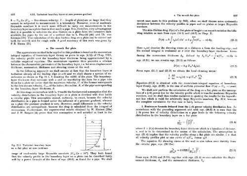
Tn thc following argument we shall assume at first that the bountlary layer is<br />
turbulent already at thc leading edge (x=0) antl we shall choose a system of coortlinatcs<br />
as shown in Fig. 21.1, h tlcnoting the width of the plate. The boundarylayer<br />
thickness O(x) increams with x antl on translating the tlatn for n pip into<br />
t.hose for a j)lat.e we not ic:c that the maximum velocity, U, of the former corrrsponds<br />
to thr free-stream vclrx:ity, U,, of thc lnttcr, the rntlius, R, of thc pipc corresponding<br />
to the boundary-laycr thickness, b.<br />
At this stage wc introduce with I,. I'ranrltl the fundamental assumption that the<br />
vr4ocit.y dis~ribution in tlic bonnclary lnycr on a plate is idcnticnl with tht inside<br />
a c.ircular pipc. This assumption cannot, ccrtainly, be exact, because the velocity<br />
rlist,ribnt.ion in a pipc is formed unclcr the influence of a pressure gradient, wllcrcas<br />
on a platr t,hc prcssurc gradient is zero. However, small differences in thc velocity<br />
clistribntion arc unimportant, bcca~~sc the drag is calculated from the intrcgral of<br />
morncntum. I~urtllrrrnorc, thc cxperimcntal results obtained by M. IIansen [23a]<br />
ant1 .J. IW nnrgrrs [6] prove that this assumption is well satisfied at least in the<br />
Y<br />
Fig. 21.1. Tnrbulent, boundary lnycr<br />
on n flnt plab nt zero iricidcnce<br />
mrrgc of rnotlrratcly large Rrynoltls nurnbcrs (IJ, l/v < 10" They hot11 found<br />
that thr vrlority profilc in thc bountlary laycr on a plate can be described fairly<br />
well hy a powrr formnh of thc form of eqn. (20.6), as found for a pipe We shall<br />
revert once more to this problem (p. 643), when we 'shall discuss some systematic<br />
deviations between the velocity profiles in pipes and on plates at larger Rcynolds<br />
numbers.<br />
The skin-friction drag D(x) of a flat plato of lenght x on onesidcsatisfics the follo-<br />
wing relation as seen from eqns. (10.1) and (10.2) in Chap. X:<br />
IEerc to(%) dcnotes Lhe shcaring stress at a distnrlcc x from tl~c Icading rtlgo, :~lld<br />
the secor~d integral is evaluated at x over the boundary-layer thickness. Introd<br />
ducing the momentum thickness d2, dcfincd by A, 1Jm2 = / 7l(r!, - TI) dy ill<br />
eqn. (8.31), we can rewrite eqn. (21 .l) as follows:<br />
From eqns. (21.1) and (21.2) we obtain the local shcaring strcss :<br />
Equation (21.3) is identical with thc monlent,lrn~-int,cgral equation of ho~~~~dary-<br />
layer theory, eqn. (8.32), in thc case of uniform potential flow U(x) .= IJ, -- COIIS~,.<br />
We shall now perform thc calculation of the drag on a flat plate on the assump-<br />
tion of a f-th-power law for tho velocity profile which is trrro for modcrntc Royriolds<br />
numbers, and we shall then confinc onrselves to quoting thc results for thc hgarith-<br />
mic law which is valid for arbitrarily largc Itcynolds numbers, Fig. 20.4, bccarrsc<br />
the complete calculation for this case is fairly tedious.<br />
1. Resistance formula deduced from the 4 -th-power velocity distribution Inw. 111<br />
accordance with the preceding argument and with eqn. (20.6) it is seen that the<br />
+-th-power law of velocity distribution in a pipc leads to the following volonity<br />
distribution in the boundary layer on a flat plate<br />
whcrc d = B(x) tlcnotcs tho I~oun~lnry-layer ~II~CICIICSR wl~ioh is a function of rlist,nnt-r-,<br />
x, and is to bc clclcrminctl in thc course of thc calculation. 'l'hc :msumption in<br />
cqn. (21.4) implies that the velocity profiles along a Rat pletc arc similar, i. e. that<br />
all velocity profiles plot as one curve of n/U, versus y/d<br />
Tllc equation for shcaring stress at the wall is also taken ovrr tlirwtly from<br />
the circular pipe, cqn. (20.12a) :<br />
.From eqns. (8.30) and (8.31), togcthcr wilh cqn. (21.4) we o:~n ca1culat.c t,l~c tlispl:tcemcnt<br />
thickness, dl, and thc momcntnn~ tliickncss, (1,:<br />
637