
You also want an ePaper? Increase the reach of your titles
YUMPU automatically turns print PDFs into web optimized ePapers that Google loves.
(22.26) vi11k11. 'S11r reql~ircrl int,cgrnls can bc writkrn in closed form, and we obt,ain<br />
-<br />
with 1) = 0.162, -- 2(1 4 1)) /?, = 04127, c = 4.0, r = 1 + (3 -+- 28) p and n =<br />
I -1 2 (1 -1- b) p. I'or n givcn vnlr~c of p t h shnpc factor is Il(z) == const,. 'l'hia means<br />
t.hnt, for 11(:1.) - .7:p IVD arc tlcnling will1 n sdf-sirnilnr solrgtion (cquilil~rir~r~~ I,ountlnry<br />
Inyrr). 'I'ho c:nsc p 5 0 rq)rewnI..s n Il:rt plnt.o at zrro incitlcnce wit,11 lJ(:r) = U, =<br />
co11st..<br />
08<br />
0 7<br />
O' O.? dL 0:6 i8 1.;<br />
lheory<br />
0 02 OL 06 08 10<br />
X<br />
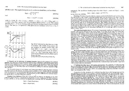
Fig. 22.10. Tnrhnlrnt honntlnry - laver . on a bodv<br />
of rrvolution with initially strong prcssnrc tine<br />
end tmnsition to constant prrssnre [R4]; cnac<br />
Sdrnt 4000: ii - (x - XI)/(% - XN), where xl<br />
= initial measuring station (start of meaaure-<br />
rnrnt). ZN = find measuring station (end of<br />
n~cnsurrmcnt ). Measured pointi by Mosrs (case 5)<br />
<strong>Theory</strong> (fnll line).<br />
a) ILynolcls nnrnher R1; b) shape factor Ill2 6. Rc~narks on the behnviour of turLulent boundnry layers in the presence of n pressure<br />
grndirnt. 'Slw applicntinn of the method described in Chap. XXIlb4 to turbulent boundnry layers<br />
lrndn 11s to the cnlc~~lation of the vnrint.ion along the llow of the Reynolds number Ra(z) fornlcti<br />
wit11 tlm energy t,l~ivkneru, fin(%), and of that of the modified shape factor H(z). Adrlitional quantitics<br />
pcrtnining to the bonndnry In.yer cnn be obtnincd hy adding .the re la ti or^^ depicted in Figs.<br />
22.6 and 22.7.<br />
,<br />
I . hr Ilr,ynoltla stressos (lo not change rn~trh dong strna~nli~~rs in rclnl.ivnly short t ~~rb~~le~t<br />
hn~nthry litycrn in 1.11~ ~~rcscn(.c of atFOng p'W8111.C gradicnLq. It. O. Doissler 1261 dc~nonstmte~l<br />
that, t,hc n~snn~pt.ion ofa constant shnaring stress can lead to good agreement betarell ealcr~lat.ion<br />
and ~ncnsnrcmrnt ; Ito also snccccded it1 calculating heat-t.rn118fcr coeflicients for tr~rbul~~lt bollnd.<br />
nry 1:tyrr.s 1261 by tho nsc of the same met.hod.<br />
I<br />
Boundnry layer tl~ickness: When tho vnlucs of II(k) n.rc know11, t,he diagram in Fig. 22.0<br />
yields the reln.tion 111z(a.) = 1ftz[1f(z)l and Ilzn[ll(~)J 111 turn, employing the deAnit.ions given<br />
in eqna. (22.31), c), we ran cnlcnlate the disj~laoen~ent thickness and the motnent11111 thicklless<br />
I). 'I'hr rnlc~tl:rf ion of t.\vo-dimrnnion;II I.nrbnlrnt. hom~tlnry Inyrrs 687<br />
rcspcctively. For cqvilibriuni bowdwy laynr~ for which Ille(z) = eonst nnd Ilm(r) - ro~~st.<br />
we obhin<br />
hl(z) - &(x) - &(x) - z(I-~D)~"+~),<br />
as seen from eqn. (22.281~).<br />
Total drag: 'The form drng of n hody in a &ream consisb of skin frirtio~~ ant1 I~~CSSIIIC tlr:~~.<br />
Tho skin friction is the integral of shearing stresses taken over tho surface of thc body. 1Svon in<br />
cnnna \viIll~w~t ~rpn~~:~.l~in~~ it in nc(:cunary to n01l 1.110 prn.s.viirc flr(~q tm skin frif4ion. 'I'h(- ~ri~il~ of<br />
the 1)rcssurc tlrng lies in the f~wt that thc boundtiry Isycr cxcrh a displncctncnL artit~n OII 1l1o<br />
external utream. 'l'l~c stren~nline of the potential flow are displaced from the contonr of the hody<br />
hy nn amotrnt, eqnnl to t,l~c tlisplncement thickncrrs. This motlifirs sorncwhnt thn prmsrlrr rlistrilmtion<br />
on tlte bwly ~nrfnoc. In contrnst wit.11 poLc:ntial llow (cl'Alcn~bwt's ~~TILIIOX). Iht: rcs~~It.i~(~t<br />
of this prcsnnrc disl.~~ibnLion ~notlilirtl 11y friclion no Irmgrr vnnisl~r~ ~IIIL prvd~~rw n 1)rrswrc drng<br />
which IIIII~~. be added t,o skin friction. The two togeLhcr givo lorw drog. '1'111- c-nlrnlntion ol- for111<br />
drag which is determined by t,lle momcntnm tl~irkncss at t.hc t,rniling edge will ho tlisc~~sscd in<br />
det.ail in Chap. XXV.<br />
Non-sepnrntina boundnry layers: Thc ~~rcnuurc drag remains smnll only if scpamtion mn be<br />
avoitled. 'Shis cnn be nchicvctl by llw I)ropc!r clc~ign of t.he nhnpc of tho 1)otly. 'l'hc srlf-~imilnr<br />
Inminnr flowu dincnss~d in (;thnpn. Vl 1 1 and IX tillbrcl cxnlnplcfl of flows whic:h (10 nol. Irnd to<br />
separation in the prtxence of an adverse prcssnrc gradient. When 1.h~ external flow follows the<br />
power law U(z) - zp, separation occun in lnminar flow for values of ps < --0.09. Thr corrcsponding<br />
value in tr~rt~ulcnt flow is obtnined from cqn. (22.28b) by suhstitdng in it. N = Ns < 0.723.<br />
Thi~ qivw p~ < - 0.27, wherem A.A. Townsend [IlOa] indicntm the valrre ps < - 0.234. This<br />
nignifien tllat a tnrhulcnt honndnry lnyer cnn sustain a considerably lnrgcr adverso prcsaurc<br />
grdicnt. wilht~t, srparnling t,l~nn tlocn n Inmin~w h~ndnry lnycr. Self-nimilnr nnl~~l~ion givf* 11 hint,<br />
on how 1.0 nrr~rngc? 1.110 prr-vxurn dinlribation ill ortlt?r In) n~~skrin 1hc 111r4(wt. ponnilh IIIIVI'~H(! JlrI~HHIIIo<br />
gradient without separation. A pressure dislribution that stark wiLh a large and continues with<br />
n decren.hg adverse pressure gradient generates a thinner boundary laycr and makes it possible<br />
to ~~~stnin n Inrgo t,otnl I)ressnro incrrn~c t.llnn n, uniform gratliont, wonltl. This fact wnn rt~nfirmrd<br />
cxporirnontnlly by G. U. Sc11ul)auor and W. C. Sl~nngor~borg [!I&!] rrnd by B. S. Ft.reLl;,rtl (10.iJ. I\<br />
critical review of different methods of calculating the position ot the point ol' separation is contnined<br />
in [17].<br />
Re-attaching boundary layers: More recent contrilmtions concerning t.lm partic.ulnrly intcresting<br />
me when a separated shear layer re-athchos itnclf to the wall and clcvelops furt,l~er as a<br />
boundary layer in the downstream direction arc rontainctl in the papor 11y 1'. Rr1rtls11:iw ~rncl 1'. Y.<br />
F. Wong 1141 na well na P. Wauschkuhn and V. Vnmntn ltnm 11 171. The tliscussion rclatrs to a<br />
boundary layer which has separated at a backward-facing stcp. The esscntinl dill'crcncc bct\vecn<br />
such a houndary layer and a "normal" boundary layer, for cxamplc on n flnt pla.te or nn aerofoil,<br />
consist8 in the fact that its turbulcnce structnre h~ hcromc st.rong-ly disturbed by the prior<br />
separation. Such a pcrtnrhation in st.ructure n~altcs it very climcult to formulate a proccrJurc for<br />
calculation. P. Wanschltuhn nnd \'. Vnssnta Ram [I 171 report measurements of wall nhcar stress,<br />
mean-velocity disttihntion and Reynolds ~t,ress in the rc-attached laycr and describe romparisons<br />
with uevcral evalunt,ion procedures.<br />
7. Turbulent boundary layem with suction and injection. The possibility of ir~flncncing the<br />
Bow in a boundary lnyer by blowing or snction in of some practicnl iniportnnco. parlicnlnrly with<br />
a view to increasing the maximum lift of aerofoilu. The promd~~ro for cnlculnting laminar boundary<br />
layers with suction was given in Soc. XIV h; tho corresponding mcthotl for a b~rhr~lrnt. ho~~~~tlary<br />
laycr wns discusbed in Scc. XXIa.<br />
A procedure for the calculation of a tnrhulcnt houndary laycr with I~omogenrous<br />
suction<br />
and blowing on a flat plate at zero incidence wna first fortnulatcd by H. Schlichting [!)0]. Expcri-<br />
mental invcstigatione and a comparison between them and theory were discvbed in See. XXIa.<br />
The preceding procedures were extended by W. Pechau [75] and lt. Eppler [32] to inclnde the<br />
ewe of an arbitrary velocity distribution -vo(z) of suction velocity. The rtxulk obtained by<br />
these methods are discussed in [92, 941. They contain further calculations performed with the aid<br />
of this procedure; they illustrate the effect 01' the magnitude and position of the suction zone on<br />
the minimum suction flow required to eliminate sepnrstion on ncrofoils. It turns out that the<br />
optimum arrangement is to concenLrate the auction zone in a narrow region on tho suction side<br />
of the mrofoil and to place it at n short distance behind the noso. This is undcrstnndahlc, beca~~so