
You also want an ePaper? Increase the reach of your titles
YUMPU automatically turns print PDFs into web optimized ePapers that Google loves.
CHAPTER XXV<br />
Determin~ation of profile drag<br />
a. General remarks<br />
The tdal tlrag on a Ijotly placctl in a stream of fluid consists of ski~r./;iction<br />
(equal to thc intcgml of all sllrnril~g strcsscs takcn over the surface o ~~~lle botly)<br />
ant1 of Jorm or prewurc, drag (integral of normal forces). Tho sum of th6 two is called<br />
told or pro/ils tlmg. The skin friction can bc c:LIcIII~~~ with some accuracy by the<br />
rise of the rncthotls of the prccccling chaptrrs. The form drag, dhich docs not exist<br />
in frictionless subsonic flow, is due to the fact that the presence of the boundary layer<br />
modifics the pressurc distribl~t~ion on t,he body as compared with ideal flow, but its<br />
comput~ation is very difficult. Consequently, reliable data on total drag must, in<br />
general, bc obtained by measurement. In more modern times methods of estimating<br />
the amount of profile drag have, nevertheless, been established. We shall discuss them<br />
bricfly in See. d of the present chapter.<br />
1.1, many cascs the tlcbrminatio~~ of total drag by weighing lacks in accuracy<br />
bccarisc, when mensurc~rlrnts arc performed, for example, in a wind tunr~el, the drag<br />
on the suspension wires is too largc compared with the force to be measured. In some<br />
cases even, such as in frec flight cxperimcnts, its direct determination becomes impossible.<br />
In such cases the mctliotl of tlctermining profile dmg from the vclocit,y<br />
tlis~rih~t,ion in the wdzc (I'itot travrrsc method), which has already bccn clescribcd<br />
in Chap. IX, 1)ccotnrs vcr.y ~uscful. Morcover, it is often the only practicable way of<br />
pcrforrning this kind of mcasr~rcment. In priuciple it can ody be used in two-tlimensional<br />
and axially symn~ctricn.l cnscs, but we shall restrict ourselves to the consitleration<br />
of tho two-dimcnsiontd casc.<br />
Thc formula in cqn. (9.2'7) which was tlcdacec~ in Chap. IX and whidi serves to<br />
dctcrn~inc the magriitutle of drag from thc v~locit~y distribution in the wake is valid<br />
only for com~)arat,ivcly large ctisbnces from the body. According to it the total drag<br />
on a botlyt is givcn 11y tlic cxprcssion:<br />
+m<br />
1) ==~Q/U(U,--u)dy. (25.1)<br />
y= -OD<br />
Tlcrc h tlrriot,rs the Irngt,ll of the cylindrical body it, the direction of thc axis of the<br />
cylinder, I/, is the frcc-stream velocity, and u(y) dcnotcs thc velocity distribution<br />
t In Cllnp. TX tho totnl drag or1 a ldy ~.la<br />
111 this chnptcr Llic sy~llbol U is used for iL.<br />
tlrnokd hy 2 I) (for tho two ~idtxi of the plate);<br />
b. The expcrimentol method due to nets 759<br />
in the wake. The integral must be taken at such a large tlistancc from the body that<br />
the static pressure at the measuring section becomes equal to that in tlic untlisturbctl<br />
&ream. In practical cases, whet,hcr in a wind tunnel or in frec flight incas~~remcnt,s,<br />
it is necessary to come much closer to the body. Consequently it becorncs nrcessnry<br />
to take irho account the c~nt~ribution from trhe pressure brtn and eqn. (26.1) nlctst<br />
be modified. 'l'his correction term has an appreciable vhluc whcn mcasummct~t,s arc<br />
performed close to the body (e. g. at distances lcss tlh onc clmd in tho case of<br />
aerofoils) and it is, therefore, important to have a comp~rativcly accuratc exprcswion<br />
for it.. The correction term was first calculatccl by A. I3ctz 141 and later by 1%. Rf.<br />
tJorrcs [2G]. At prcsct~t~ most mcasuremcnb arc bcing cvalu:~tccl wilh t,l~o :&I of t.116<br />
formula clue to Jones because of its compamt,ive simplicit,y. Ncvcrihrlcss, we propose<br />
t.o cliscuss Bet,z's formula as well becausc it* clerivatkm cxhibits scvcm.l very<br />
iritIcrcstting features.<br />
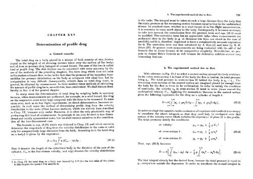
b. The cxperirnentnl method due to Betz<br />
Wit.11 rcfcmnet: to I'ig. 25. I we s~lcct a control surface around tho 1)otly as sliow~l.<br />
In thc rnbry cross-section 1 in front of the botly the flow is loaslcss, its total pressure<br />
being g,. The total prcwurc in cross-scct.iori I1 I)chintl tho hotly is !j2 ,: (I,.,. '1'110<br />
remaining cross-srctions of the control surf;lcc arc imaginctl placed far cnoirgl~ from<br />
the body for the flow in t81iem to be untlistorbecl. In order to satisfy the condit.ion<br />
of continuity, tl~e velocity u2 in cross-sect.ion It niust in some places cxccccl t,he<br />
11ndist,ur1)~tI velocity 11,. Applying tlic moinentwn tlrcorcrn to the cont~rol surf:~c:c<br />
gives t.11~ following expression for the drag on a cylinder of length h:<br />
In order to atlapt this rq~li~tion to the cvnluation of cxpcri~ncn~~nl rcsn1t.s it, is nct~eswary<br />
1.0 t,mnsfornt the above int,cgmls so that they necd hrdy be cvn1unt.c.d owr Illat.<br />
sect,ion of the velocit,y curve which includcs the dcpression of plarlc: I1 in t,hc profile.<br />
The total pressures satisfy the conditions:<br />
I<br />
;it. inlinit.y:<br />
900 = ~ r+ n e um.z<br />
The first integml already hns the tlcsirrcl form, 11cm11sc the total prcssrlrtx is rt111aI t,o<br />
g,, rvrrywlierc outsidr thc tleprcssion In order to transform the scco~~tl inirgml in