
You also want an ePaper? Increase the reach of your titles
YUMPU automatically turns print PDFs into web optimized ePapers that Google loves.
XXV. 1)obrlninalion of proRlo drag<br />
included the solidity ratio 111 (= 0.6, 0.76, 1.0 and 1.25); the blade angle was Ps =<br />
30" (turbine cascade). The loss coefficient defined in eqn. (25.33) is seen plotted in<br />
terms of the dcflcxion cocfficient or deflcxion ratio<br />
ad = Awd/?l~,, ,<br />
where AN?, tlcnolcs 1.h~ tm.r~svcrsc compor~cnt of vclocit,y (i.'e. vclocit,y in circomferential<br />
direction) created by the cascade. If we first center our attention on the<br />
middle range of the polars (adhering boundary layers), we notice a steep increase in<br />
the loss coefficient which occurs as thc solidity ratio decreases. The reason for it lies<br />
in the fact that the number of bladcs per unit of length of the circumference is larger<br />
when the pitch is small than when thc pitch is larger. To a first approximation the loss<br />
coefficient is proportional to the number of blades. At the right and left edge of the<br />
polar we observc a sudden and large increase in the loss coefficient. This is due to flow<br />
separation on the pressure side (left end of curve) or on the suction side (right end of<br />
polar) of the bladc. In the latter case, an increase in the flow angle causes the admissible<br />
load on the blade to be exceeded. It is remarkable that the polar curves displace<br />
themselves in the direction of largcr angles of deflexion as the solidity ratio decreases.<br />
The ~ncasurcmcnts a.nd the calculat.ions were carried out for a Reynolds number<br />
R -. to, llv - 5 x 10% .TIC calculations wcrc performed on tho assumption that thc<br />
bountlnry hycr was turhulcnt. all along the hlatlcs. In the oxpcrin~ontal nrmngcrncnt<br />
the boonrlary layers wcrc made turbulent by the provision of tripping wires ncar<br />
the leading edges. Thc calculated and measured values of the loss coefficient show<br />
very good agrccmcnt with cnch other. Furthcr examples and comparisons between<br />
theory and experiment are givcn in [47, 631.<br />
Wake: A very dctailcd experimental investigation of the flow in a turbulent<br />
wake bchind a cascade of blades is described in a paper by R. Raj and B. Laksh-<br />
minarayana [42]. Measurements included determinations of the velocity distribution,<br />
intensity of turbulencc, and of the apparent Reynolds stresses in the wake at different<br />
distances from the cascade. It has transpired that the wakes are not symmetric up<br />
to a distance (314) 1 bchind the blades in cascades which turn the flow. The decrease<br />
in velocity downstream from the cascade exit section is considerably slower than at<br />
a flat plate, behind a circular cylinder or downstream from a single aerofoil at zero<br />
incidcnce.<br />
Jet flnp: The angment,at,ion of the turning angle A,'? = Dl - p2 of colnpressor<br />
cascades by a jet flap has been investigated by U. Stark,[G4a].<br />
2. 111flue11ce of Reynolds number: Thc chnngcs in the aerodynamic coefficients of<br />
n cascadc protlucctl by a chnngc in l,hc itcynol(1s nnmber arc import,n~~l whcn it<br />
becomes ncccssary to apply the results of tcsts on models to thc design of a fullscale<br />
turho~nachine. This effcct is excrtetl principally on the loss coefficicr~t, and<br />
the can be found discussed in a sizeable umber of publications 15, 41, 651.<br />
From tho physical point of view, the cffect of Rey A" olds number on the loss coefficient<br />
of a two-tlimcnsional cascndc is analogous to that of the skin friction of a single aerofoil:<br />
hccausc in eit.her case the cffect originates in the boundary layer. The losses<br />
sufTcred by the cascatlo stem mainly from the boundary layer if the pressure distribut,ion<br />
dong a I)latlo in n cascadc is such that no imporhr~t scparntions occur.<br />
'l'hry nro t,hcn ak:rl.otl hy tllc Ttcynoltls number in aho~lt t,ho same way as t,he skin-<br />
I<br />
friction coefficient of a flat plate at zero incidence arid are proportional to R-'12 for<br />
laminar flow, becoming proportional to R-lI5 in turbulent flow. In both cases, the<br />
Reynolds number is formcd with the blade length, I. Thc dcpcndcnccof t.hc loss cocffi-<br />
cient on Reynolds number in the absence of separation can be determined by calcu-<br />
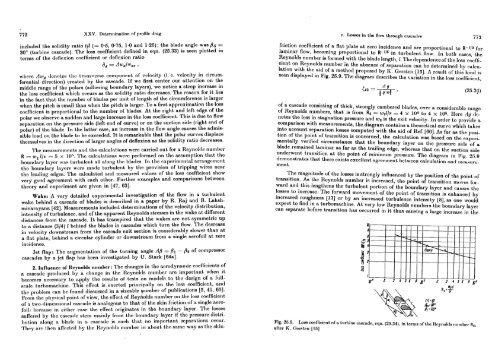
lation with the aid of a method proposed by K. Gersten [15]. A rcsult of this kind is<br />
seen displayed in Fig. 25.9. The diagram describes thc variation in the loss coefficient,<br />
A g<br />
(12 = -<br />
;be4 ' (25.84)<br />
of a cascade consisting of thick, strongly cambered bladcs, over a considcrablo range<br />
of Reynolds numbers, that is from Rz = wzllv = 4 x lo4 to 4 x 10⁵. I-Icre Ag dcnotes<br />
the loss in stagnation pressure and iuz is the exit velocity. In order to providc a<br />
comparison with mensurcmenta, thc diagram contains a thcorctical crrrvc which tnkcs<br />
into account separation losses computed with the aid of Ref. [GO]. As far as the position<br />
of the point of transition is conccmed, the calculation was based on the expcrimentally<br />
verified circumstance that the boundary layer on the pressure side of a<br />
blade remained laminar as far as the tmiling edge, whcreaa that on the suction side<br />
undcrwcnt transition at the point of minimum pressure. Thc dingmm in Pig. 26.9<br />
demonstmtcs t.hnh thcrc cxist.~ cxccllcnt ngrccrncnt I~cLwccn oalcnlntiotl nnql rtltrclrrilrament.<br />
The magnitude of the losses is strongly influenced by t.he position of the point of<br />
transition. As thc Rcynolds numbcr is incrcnscd, tho point of transition movcs for-<br />
ward and this lengthcns the turbulent portion of the boundary layer and causes the<br />
losses to increase. The forward movemcnt of the point of transition is enhanced by<br />
increased roughness 1131 or by an increased turbulencc intensity [a], as one would<br />
expect to find in a turbomachine. At very low Rcynolds numbers the boundary laycr<br />
can separate before transition has occurred in it thus causing a large incrcasc in thc<br />
Fig. 25.0. Loss coefficient of a turbine cascade, eqll. (25.34). in brr~rs of the Rryl~oltls tl~it~~bcr Rz,<br />
after I