Create successful ePaper yourself
Turn your PDF publications into a flip-book with our unique Google optimized e-Paper software.
082<br />
XXII. Thc incomprm~il~lr L~lrbtrlolt bn~rndnry lnyrr<br />
wherc bhr following numerical vnlncs (cf. Table 22.2 - energy method) have been<br />
employed :<br />
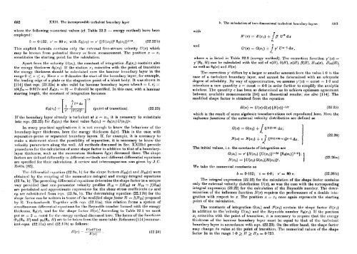
b = 0.152; v' .= 80 v; with flq(rI) = v' {[U(r1)J2 R3(xl))lCb.<br />
(22.22 b)<br />
This explicit formula cont,nins only t.hr extmnal free-strcam vclocity U(x) which<br />
mny IIC known from pot,cnt,ial t.hcory or from mcasarement. The positmion .2: = xl<br />
constit.ntes t,he st.nrt,ing point for t,he calculation.<br />
Apart from the velocity U(xl), the constant of integrntion E3(rl) rontains also<br />
the encrgy thickness 63(.cl). If the station xl coincides with the point of transitmion<br />
the cnergy thickness should be ralc~llatcd over the laminar boundary layer in t.hc<br />
rangc 0 2 x xl Here x = 0 rlenotcx thc start of t,he boundary layer; for example,<br />
the leading edge of a plate or the stagnation point of a blunt body. It waa shown in<br />
11141 that eqn. (22.22a) is also valid for laminar boundary layers whenb = 1, vi =<br />
v/Q& = 0.91 7v and lC3(xl = 0) = 0 should be specificd. In this case, with a laminar<br />
starting length, the constant of integration becomes<br />
112<br />
(point of transition). (22.23)<br />
If the boundary lnyer drcntly is t,urbulent at z = XI, it is necessary to substitute<br />
into eqn. (22.22) for E3(z1) t,he local vnlue R3(x1) = n3(x1) U(xl)/v.<br />
In many practirnl npplicnt.ions it. is not enough to know the \)cl~aviour of t,hc<br />
boundary-layer thickness, lwre t,hc encrgy t.hickness &(x). This is the case wit,h<br />
ueparation-prone or separat,ctl boundary hyers. If, for example, it is necessary t,o<br />
makc n statcmcnt about t.he possibiliby of separation, it is necessary to know the<br />
velocity parameters along the wdl. All mct,hods discussed in Sec. XXIIbl provide<br />
procedures for t,he calouletion of sonir xhnpe fnctor in addition to tht of a boundarylayer<br />
t~liiclrncsx, such as the niomcnt,~~m thickness &(x) discussed t.here. The shapc<br />
factors nre defined differently in diff'rrent methods and different differential equations<br />
are specified for thcir ralrnlation. A revicw and intercomparison was given by J.C.<br />
Roth [85].<br />
l'hc diPFrrcwt,inl rq11r21~ion (22.!h, 1)) for t.hc shnpr. factors 1132(x) and Hz3(~) were<br />
obtained by tlic coupling of thc ~~ior~~rnturn-integral and energy-integrnl equnt.ions<br />
(22.78, b). Thc pereding dilTrrent,inl equntions det,ermine the shape factor in a unique<br />
way proviclrcl that onc-para~net~cr velocity profiles Hlz.= f(H32) or Hlz = f(Hm)<br />
nrc post,ulnt,ctl and npproxiniak cxprrsxions for t,he shear-stress coefficients CT and<br />
co are s~hst.itllt.c11 from rqn. (22.Rn, b). The dct,crmining equntion (22.11b) for thc<br />
shapr factor cnn br writ.tm in t,crms of thc naodijied shape lactor If = f(llzs) proposed<br />
by 15. l'r~~rlrcnl~rotlt.. l'ogcl.hcr with rqn. (22.11a), this relnt,ion forms a system of<br />
simultn.rous tliffrrrnhl equations for t,l~e Reync~lds number formed wit,h t,lte energy<br />
t,hickncss, Ra(:v). and for thc shapt factor 11(a)! According to Table 22.1 we must<br />
put TN -.- 2 =- const 1tr1 Ihr rnrlgy ntcthotl clisrussed herc 7'hc forms of the funrtions<br />
cl,3(RR, 11) nnd lli3(R3. If) arr lo Irr taltrll Irom thc same talrlc Rcference[ll4]summarizci<br />
cqns (22 1 I n) nntl (22 1 1 0) as follows :<br />
with<br />
and<br />
Z<br />
G1(x) = G(q) + j y' un-' dx,<br />
where n is listed in Tablc 22.2 (energy method). The correction function y'(x) =<br />
yf(R3, H) can be calculated with the aid of a(ll), b(H), u(H), /l(II), If12(x), 1fS2(H),<br />
as well as R3(2) and N(x).<br />
The correction y' differs by a larger or smaller amount from the value 1.0 in the<br />
case of a turbulent boundary layer, nnd cannot bc determined with an adrqunte<br />
degree of reliability. 13y way of approximation, we assume y'(x) = const = 1.0 and<br />
introducc a new quantity c = const = 4.0 in order further to simplify the analytic<br />
solution. The qunntily c has been. so dct~ermincd as to nchicve optimum ngrccmcnl<br />
between available measurements [64] and theoretical results; see also [114]. The<br />
modified shape factor is obtained from the equation<br />
which is the result of somc algchraic txansformations not reproduced Itcrc. llerc thc<br />
influence /unctions of the external velocity distribution are defined os<br />
The initial valuw, i.0. the constants of intcgration are<br />
We take the numerical constants as<br />
The integral expression (22.25) for the calculation of the shape factor contains<br />
only the external velocily distribution U(x), as was the case with the corresponding<br />
integral expression (22.22) for the calculation of the Rcynolds number. The detm-<br />
mination of the inllucncc function N(r) rcquircs thc pcrformnnco of n doublc inLc-<br />
gration with respect to x. The position x = xl once again represents the starting<br />
point of the calculation.<br />
The constants of integration G(s1) and N(xl) contain the shape factor lI(xl)<br />
in addition to the'velocity U(xl) and thc Reynolds number R3(xl). If the position<br />
xl coincides with the point. of transition, it, is necessary to require that the encrgy<br />
thickness of the laminar boundnry layer must be equal to that of the turbulent.<br />
boundary lnyer in accordance with eqn. (22.23). On the other hand, the shapc factor<br />
may change it.s value at the point of trnnsition. The numcricnl values of bl~c shapc<br />
fnctor lic in t,hc mngc 1.0 2 11 2 Ils = 0.723.<br />
2,


