- Page 1 and 2:
SERVICE SPECIFICATIONS SERVICE DATE
- Page 3 and 4:
Output Shaft End play 0.3 - 0.9 mm
- Page 5 and 6:
EQUIPMENT Feeler gauge Vernier cali
- Page 7 and 8:
Rear Planetary Gear Planetary pinio
- Page 9 and 10:
AT-10 PREPARATION SST (SPECIAL SERV
- Page 11 and 12:
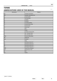
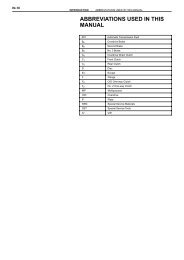
IN-10 INTRODUCTION - ABBREVIATIONS
- Page 13 and 14:
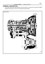
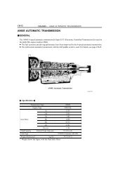
GENERAL SPECIFICATIONS Type of Tran
- Page 15 and 16:
GENERAL SPECIFICATIONS Type of Tran
- Page 17 and 18:
2. FUNCTION OF COMPONENTS COMPONENT
- Page 19 and 20:
2 or L Position 2nd Gear L Position
- Page 21 and 22:
4. ELECTRONIC CONTROL SYSTEM The el
- Page 23 and 24:
2. FUNCTION OF COMPONENTS COMPONENT
- Page 25 and 26:
2 or L Position 2nd Gear L Position
- Page 27 and 28:
ECTS Throttle Position Sensor Idli
- Page 29 and 30:
Manual Valve Lever Shaft ♦ Oil Se
- Page 31 and 32:
A46DE AUTOMATIC TRANSMISSION - COMP
- Page 33 and 34:
A46DE AUTOMATIC TRANSMISSION - COMP
- Page 35 and 36:
A46DE AUTOMATIC TRANSMISSION - COMP
- Page 37 and 38:
SST A46DE AUTOMATIC TRANSMISSION -
- Page 39 and 40:
A46DE AUTOMATIC TRANSMISSION - COMP
- Page 41 and 42:
Manual Valve Lever Shaft ♦ Oil Se
- Page 43 and 44:
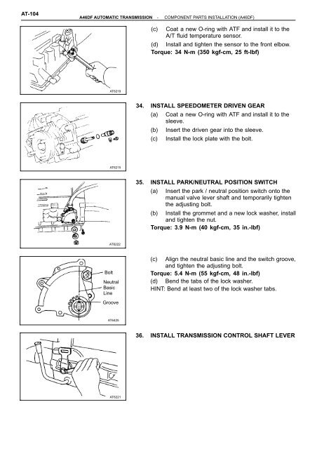
A46DF AUTOMATIC TRANSMISSION - COMP
- Page 45 and 46:
A46DF AUTOMATIC TRANSMISSION - COMP
- Page 47 and 48:
A46DF AUTOMATIC TRANSMISSION - COMP
- Page 49 and 50:
SST A46DF AUTOMATIC TRANSMISSION -
- Page 51 and 52:
A46DF AUTOMATIC TRANSMISSION - COMP
- Page 53 and 54:
AT-24 COMPONENT PARTS GENERAL NOTES
- Page 55 and 56:
AT-26 Front Side Bushing A46DE AUTO
- Page 57 and 58:
AT-28 A46DE AUTOMATIC TRANSMISSION
- Page 59 and 60:
AT-26 Front Side Bushing A46DF AUTO
- Page 61 and 62:
AT-28 A46DF AUTOMATIC TRANSMISSION
- Page 63 and 64:
AT-30 AT4751 AT4752 A46DE AUTOMATIC
- Page 65 and 66:
AT-32 A46DE AUTOMATIC TRANSMISSION
- Page 67 and 68:
AT-34 AT4578 AT4765 Retainer Retain
- Page 69 and 70:
AT-36 Hold Lock A46DE AUTOMATIC TRA
- Page 71 and 72:
AT-30 AT4751 AT4752 A46DF AUTOMATIC
- Page 73 and 74:
AT-32 A46DF AUTOMATIC TRANSMISSION
- Page 75 and 76:
AT-34 AT4881 AT4765 AT4578 AT4765 R
- Page 77 and 78:
AT-36 Hold Lock A46DF AUTOMATIC TRA
- Page 79 and 80:
AT-38 A46DE AUTOMATIC TRANSMISSION
- Page 81 and 82:
AT-40 Front Rear A46DE AUTOMATIC TR
- Page 83 and 84:
O/D Planetary Ring Gear Race ♦ No
- Page 85 and 86:
A46DF AUTOMATIC TRANSMISSION - OVER
- Page 87 and 88:
A46DF AUTOMATIC TRANSMISSION - OVER
- Page 89 and 90:
SST A46DE AUTOMATIC TRANSMISSION -
- Page 91 and 92:
SST SST AT4650 AT6246 AT4838 A46DE
- Page 93 and 94:
AT-42 Front Clutch Front Clutch Pis
- Page 95 and 96:
AT-44 A46DF AUTOMATIC TRANSMISSION
- Page 97 and 98:
AT-46 AT4687 AT4688 Rear Front SST
- Page 99 and 100:
AT-48 SST A46DE AUTOMATIC TRANSMISS
- Page 101 and 102:
AT-50 SST AT4696 AT4838 AT4695 A46D
- Page 103 and 104:
Snap Ring ♦ Non-reusable part A46
- Page 105 and 106:
A46DF AUTOMATIC TRANSMISSION - REAR
- Page 107 and 108:
A46DF AUTOMATIC TRANSMISSION - REAR
- Page 109 and 110:
SST A46DE AUTOMATIC TRANSMISSION -
- Page 111 and 112:
SST AT4704 AT4839 SST A46DE AUTOMAT
- Page 113 and 114:
AT-52 Oil Seal Ring Snap Ring ♦ N
- Page 115 and 116:
AT-54 A46DF AUTOMATIC TRANSMISSION
- Page 117 and 118:
AT-56 A46DF AUTOMATIC TRANSMISSION
- Page 119 and 120:
AT-58 SST A46DE AUTOMATIC TRANSMISS
- Page 121 and 122:
AT-60 SST AT4778 AT4783 AT4777 A46D
- Page 123 and 124:
Center Support Non reusable part A
- Page 125 and 126:
SST A46DF AUTOMATIC TRANSMISSION -
- Page 127 and 128:
A46DF AUTOMATIC TRANSMISSION - NO.
- Page 129 and 130:
A46DE AUTOMATIC TRANSMISSION - PLAN
- Page 131 and 132:
AT-62 Free Hold Front Side Retainer
- Page 133 and 134:
AT-64 Open End AT4773 AT4769 Free H
- Page 135 and 136:
AT-66 A46DE AUTOMATIC TRANSMISSION
- Page 137 and 138:
AT-68 Hold Free 5. CHECK OPERATION
- Page 139 and 140:
AT-66 A46DF AUTOMATIC TRANSMISSION
- Page 141 and 142:
AT-68 Hold Free 5. CHECK OPERATION
- Page 143 and 144:
AT-70 A46DE AUTOMATIC TRANSMISSION
- Page 145 and 146:
AT-72 A46DE AUTOMATIC TRANSMISSION
- Page 147 and 148: AT-74 A46DE AUTOMATIC TRANSMISSION
- Page 149 and 150: AT-70 A46DF AUTOMATIC TRANSMISSION
- Page 151 and 152: AT-72 A46DF AUTOMATIC TRANSMISSION
- Page 153 and 154: AT-74 A46DF AUTOMATIC TRANSMISSION
- Page 155 and 156: Disc ♦ Non-reusable part A46DF AU
- Page 157 and 158: Pin Pin Retainer A46DE AUTOMATIC TR
- Page 159 and 160: Q00434 A46DE AUTOMATIC TRANSMISSION
- Page 161 and 162: Pin Pin Retainer A46DF AUTOMATIC TR
- Page 163 and 164: Q00434 A46DF AUTOMATIC TRANSMISSION
- Page 165 and 166: Mark Name (Color) A46DE AUTOMATIC T
- Page 167 and 168: AT-80 Retainer Plug Cut-back Valve
- Page 169 and 170: AT-82 RETAINERS AND PIN LOCATION Cu
- Page 171 and 172: AT-84 Mark Name (Color) A46DE AUTOM
- Page 173 and 174: Plug Pin ♦ Non-reusable part A46D
- Page 175 and 176: RETAINERS, PIN AND CHECK BALLS LOCA
- Page 177 and 178: Mark Name (Color) A46DE AUTOMATIC T
- Page 179 and 180: AT-86 Plunger Sleeve Intermediate M
- Page 181 and 182: AT-88 RETAINERS, CHECK BALLS AND SP
- Page 183 and 184: A46DE AUTOMATIC TRANSMISSION - TRAN
- Page 185 and 186: AT6267 Mark A46DF AUTOMATIC TRANSMI
- Page 187 and 188: SST AT6424 AT4803 A46DF AUTOMATIC T
- Page 189 and 190: A46DF AUTOMATIC TRANSMISSION - COMP
- Page 191 and 192: SST SST Front A46DF AUTOMATIC TRANS
- Page 193 and 194: A46DF AUTOMATIC TRANSMISSION - COMP
- Page 195 and 196: A46DF AUTOMATIC TRANSMISSION - COMP
- Page 197: C4500 A46DF AUTOMATIC TRANSMISSION
- Page 201 and 202: COMPONENT PARTS INSTALLATION Disass
- Page 203 and 204: Manual Valve Lever Manual Valve Lev
- Page 205 and 206: A46DE AUTOMATIC TRANSMISSION - COMP
- Page 207 and 208: Front A46DE AUTOMATIC TRANSMISSION
- Page 209 and 210: Race SST A46DE AUTOMATIC TRANSMISSI
- Page 211 and 212: Q00420 A46DE AUTOMATIC TRANSMISSION
- Page 213 and 214: AT6231 AT6229 A46DE AUTOMATIC TRANS
- Page 215 and 216: A46DE AUTOMATIC TRANSMISSION - COMP
- Page 217 and 218: 1992 TOYOTA MOTOR CORPORATION All r
- Page 219 and 220: IN-6 Fuse Equal Amperage Rating WRO
- Page 221 and 222: IN-8 INTRODUCTION - GLOSSARY OF SAE
- Page 223 and 224: IN-2 HOW TO USE THIS MANUAL To assi
- Page 225 and 226: IN-4 CAUTIONS, NOTICES, HINTS: Sl U
- Page 227: Class Diameter mm Pitch mm Specifie